
Manual

Using 6200 Series Software
Version 2.1 and Earlier
Appendix B
B2
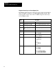
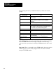
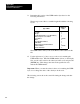
The following table tells you what information you must enter at each
prompt:
At
This Prompt:
You:
Read/Write T
oggle between READ for a read command and WRITE for a
write command.
PLC5 Data T
able Address
Enter the local data table address where data starts for the
WRITE command or data will be stored for the READ
command.
Size in Elements
Enter the message size in elements.
Local/Remote
Select REMOTE (through the 1779KP5).
Remote Station
Enter the destination NODE number
. If the USER number is
not the default (01), then you will need to manually enter it in
the control file as described later in this appendix.
Link ID
Enter the destination LINK value.
Remote Link T
ype
Select DA
T
A HIGHW
A
Y for Data Highway II or Data Highway
Plus.
Local Node Address
Enter the address of the 1779KP5.
Processor T
ype
Select the destination processor type (toggle between PLC2,
PLC3, and PLC5).
Destination Data T
able
Address
Enter the destination processor
'
s data table address.
If the USER number you use is not the default (01), you need to manually
enter the USER number in the message control file. The following
section provides a procedure for entering a USER number into the control
file.
Important: When you manually enter a USER number, the remote station
number appears to be incorrectly displayed due to how the 1784-T50
interprets the USER number.