Installation Instructions Stratix 6000 Ethernet Managed Switches Catalog Numbers 1783-EMS08T, 1783-EMS04T Topic Page Important User Information 2 North American Hazardous Location Approval 3 European Hazardous Location Approval 4 Preventing Electrostatic Discharge 6 About the Switches 7 Install the Switches 7 DIN Rail Mounting 8 Panel Mounting 10 Wire the Switch 11 Connect the Copper Ethernet Ports 12 Install an Optional SFP Module 13 Connect the Fiber Optic Ethernet Port 14 Grou
Stratix 6000 Ethernet Managed Switches Important User Information Read this document and the documents listed in the additional resources section about installation, configuration, and operation of this equipment before you install, configure, operate, or maintain this product. Users are required to familiarize themselves with installation and wiring instructions in addition to requirements of all applicable codes, laws, and standards.
Stratix 6000 Ethernet Managed Switches 3 North American Hazardous Location Approval The following information applies when operating this equipment in hazardous locations. Informations sur l’utilisation de cet équipement en environnements dangereux. Products marked "CL I, DIV 2, GP A, B, C, D" are suitable for use in Class I Division 2 Groups A, B, C, D, Hazardous Locations and nonhazardous locations only.
Stratix 6000 Ethernet Managed Switches WARNING: For 1783-EMS08T switches only, when you insert or remove the small form-factor pluggable (SFP) optical transceiver while power is on, an electrical arc can occur. This could cause an explosion in hazardous location installations. Be sure that power is removed or the area is nonhazardous before proceeding.
Stratix 6000 Ethernet Managed Switches 5 Environment and Enclosure ATTENTION: This equipment is intended for use in a Pollution Degree 2 industrial environment, in overvoltage Category II applications (as defined in IEC publication 60664-1), at altitudes up to 2000 m (6562 ft) without derating. This equipment is considered Group 1, Class A industrial equipment according to IEC/CISPR Publication 11.
Stratix 6000 Ethernet Managed Switches Preventing Electrostatic Discharge ATTENTION: This equipment is sensitive to electrostatic discharge, which can cause internal damage and affect normal operation. Follow these guidelines when you handle this equipment: • • • • • • Touch a grounded object to discharge potential static. Wear an approved grounding wriststrap. Do not touch connectors or pins on component boards. Do not touch circuit components inside the equipment.
Stratix 6000 Ethernet Managed Switches 7 About the Switches These switches provide real-time access to network data through the Logix-based control system. The switches integrate into Logix programs and update tags automatically. Use the switches to assist in continuously monitoring your network and implementing changes. The figure shows Ethernet port identification for the 1783-EMS08T 8-port and the 1783-EMS04T 4-port switches.
Stratix 6000 Ethernet Managed Switches WARNING: If you connect or disconnect the communication cable with power applied to this module or any device on the network, an electrical arc can occur. This could cause an explosion in hazardous location installations. Be sure that power is removed or the area is nonhazardous before proceeding. WARNING: If you connect or disconnect wiring while the field-side power is on, an electrical arc can occur.
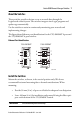
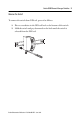
Stratix 6000 Ethernet Managed Switches 9 Remove the Switch To remove the switch from DIN rail, proceed as follows. 1. Place a screwdriver in the DIN-rail latch at the bottom of the switch. 2. Hold the switch and pry downward on the latch until the switch is released from the DIN rail.
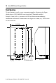
Stratix 6000 Ethernet Managed Switches Panel Mounting To panel mount a switch, create a mounting template, referring to the figure, which shows a 1783-EMS08T switch with an SFP module installed. Provide 15 mm (0.6 in.) clearance for DIN-rail latch movement during installation and removal. Dimensions in the figure are in mm (in.). These views are not actual size. 52.07 (2.05) 118 (4.64) 107 (4.21) 12 (0.47) 12 (0.47) 27.7 (1.
Stratix 6000 Ethernet Managed Switches 11 Wire the Switch Read this section for information about external power supply wiring. Provide low voltage DC power to the switch by using the screw terminals at the bottom of the switch.
Stratix 6000 Ethernet Managed Switches Follow these steps to wire the switch. 1. Be sure power to the power supply is turned off. 2. Be sure you have the proper gauge of wire for your power supply. 3. Strip approximately 0.9 mm (0.35 in.) from each end of the wire. 4. Using a Phillips screwdriver, loosen the screw terminals on the terminal strip at the bottom of the switch. 5. Connect DC+ (24V DC nominal) from the power supply to the DC+ terminal and tighten the screw. 6.
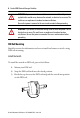
Stratix 6000 Ethernet Managed Switches 13 Install an Optional SFP Module To install a 1G fiber small form-factor pluggable (SFP) module into the fiber optic Ethernet slot on the bottom to the 1783-EMS08T switch, grasp the SFP module on the sides and insert it into the slot until you feel the connector snap into place. TIP For detailed instructions on installing, removing, and connecting to SFP modules, see the documentation that shipped with the SFP module.
Stratix 6000 Ethernet Managed Switches ATTENTION: If the SFP module cannot be fully inserted, stop! Do not force the module into the slot. Rotate the SFP module 180 degrees and try again. ATTENTION: Under certain conditions, viewing the optical port may expose the eye to hazard. When viewed under some conditions, the optical port may expose the eye beyond the maximum permissible exposure recommendations. IMPORTANT The 1783-EMS08T switch supports 1G fiber SFP modules only.
Stratix 6000 Ethernet Managed Switches 15 Grounding Considerations ATTENTION: You must provide an acceptable grounding path for each device in your application. For more information on proper grounding guidelines, refer to publication 1770-4.1, Industrial Automation Wiring and Grounding Guidelines. This product is intended to be mounted to a well-grounded mounting surface such as a metal panel.
Stratix 6000 Ethernet Managed Switches Use the Switch To start using your switch, follow this procedure. For information about the status indicators on the switch, refer to the Stratix 6000™ Ethernet Managed Switch User Manual, publication 1783-UM001. 1. Connect to your computer’s LAN card by using patch cable or cross-over cable and following these steps. a. Choose Start > Settings > Network Connections and right-click Local Area Connection and Properties. b.
Stratix 6000 Ethernet Managed Switches 17 c. From the Ethernet Protocol (TCP/IP) Properties menu, change the IP address to 192.168.1.3 and Subnet mask to 255.255.255.0. 2. Connect to the switch via a Web browser by using these steps. a. Open a browser window. b. Enter the default IP address of 192.168.1.1 in the address bar, press Enter, and note the following defaults: • User name should be left blank. • Password is PASSWORD. 3. Configure the switch.
Stratix 6000 Ethernet Managed Switches Specifications Stratix 6000 Ethernet Managed Switches Attribute 1783-EMS08T 1783-EMS04T Power requirements 12…48V DC Class 2/SELV 250 mA @ 24V DC 12…48 V DC Class 2/SELV 100 mA @ 24V DC Power dissipation 5.8 W @ 60 °C (140 °F) max 2.6 W @ 60 °C (140 °F) max Thermal dissipation 24.
Stratix 6000 Ethernet Managed Switches 19 Stratix 6000 Ethernet Managed Switches (continued) Attribute 1783-EMS08T Wire size Ethernet connections: RJ45 connector according to IEC 60603-7, 2 or 4 pair Category 5e min cable according to TIA 568-B.1 or Category 5 cable according to ISO/IEC 24702 DC Power connections: 0.33... 3.3 mm2 (22...12 AWG) solid or stranded copper wire rated at 75 °C (167 °F) or greater, 1.2 mm (3/64 in.) insulation max Functional ground connection: 3.
Stratix 6000 Ethernet Managed Switches Environmental Specifications Attribute 1783-EMS08T, 1783-EMS04T Emissions CISPR 11: Group 1, Class A Temperature, operating IEC 60068-2-1 (Test Ad, Operating Cold), IEC 60068-2-2 (Test Bd, Operating Dry Heat), IEC 60068-2-14 (Test Nb, Operating Thermal Shock): 0…60 °C (32…140 °F) Temperature, nonoperating IEC 60068-2-1 (Test Ab, Unpackaged Non-operating Cold), IEC 60068-2-2 (Test Bb, Unpackaged Non-operating Dry Heat), IEC 60068-2-14 (Test Na, Unpackaged Non-
Stratix 6000 Ethernet Managed Switches 21 Certifications Certifications (when product is marked)(1) 1783-EMS08T, 1783-EMS04T CE European Union 2004/108/EC EMC Directive, compliant with: EN 61326-1; Meas./Control/Lab.
Stratix 6000 Ethernet Managed Switches Additional Resources These documents contain additional information concerning related products from Rockwell Automation. Resource Description EtherNet/IP Industrial Protocol White Paper, publication ENET-WP001 Describes how to implement services and data objects on a TCP/UDP/IP based Ethernet network. Stratix 6000 Ethernet Managed Switch User Manual, publication 1783-UM001 Provides details about how to configure and use the switch.
Stratix 6000 Ethernet Managed Switches 23 Notes: Rockwell Automation Publication 1783-IN004B-EN-P - June 2014
Rockwell Automation Support Rockwell Automation provides technical information on the Web to assist you in using its products. At http://www.rockwellautomation.com/support you can find technical and application notes, sample code, and links to software service packs. You can also visit our Support Center at https://rockwellautomation.custhelp.com/ for software updates, support chats and forums, technical information, FAQs, and to sign up for product notification updates.