
User manual


Publication 1747-UM011F-EN-P - May 2007
110 Installing Your Hardware Components
power 24V dc sensors and loads. The terminals on the 1746-P1,
1746-P2, 1746-P5, and 1746-P6 power supply provide an isolated,
nonfused 200 mA, 24V dc power supply. The terminals on the
1746-P4 power supply provide an isolated, nonfused 1 A, 24V dc
power supply. (The 1746-P3 and 1746-P7 power supplies do not
provide for an external power source.)
Install Your Chassis
Interconnect Cable
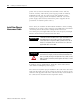
Three cables are available to link modular hardware chassis. Catalog
number 1746-C7 cable is 152.4 mm (6 in.) in length and is used when
connecting chassis side-by-side. Catalog number 1746-C9 is
914.4 mm (36 in.) in length and 1746-C16 is 1.27 m (50 in.) in length
and are used to link one chassis below the other.
.
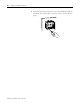
In multiple chassis configurations, install the chassis interconnect
cable before installing the power supply.
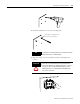
The cables are keyed for proper installation. The end of the cable that
plugs into the right socket in the chassis has the key on the top of the
connector. The opposite end of the cable has the key on the inside of
the connector for insertion into the expansion chassis.
IMPORTANT
1746-C9 and 1746-C16 cables have a rigid, unbendable shrink
wrap applied at the end of each connector, which provides
strain relief. When using these cables, provide at least 101.6
mm (4 in.) of clearance at the side of the chassis to allow for
proper bend radius of the cable.
ATTENTION
Do not use any cables other than those provided. Longer cables
could affect the integrity of data communication between the
chassis, possibly causing unsafe operation. Also, make sure the
cable is properly secured to protect against the effects of shock
and vibration.