DeviceNet Universal PCI Scanner Card 1784-PCIDS Series B Installation Instructions
Important User Information Solid state equipment has operational characteristics differing from those of electromechanical equipment. Safety Guidelines for the Application, Installation and Maintenance of Solid State Controls (Publication SGI-1.1 available from your local Rockwell Automation sales office or online at http://www.ab.com/manuals/gi) describes some important differences between solid state equipment and hard-wired electromechanical devices.
ATTENTION This equipment is intended for use in a Pollution Degree 2 industrial environment, in overvoltage Category II applications (as defined in IEC publication 60664-1), at altitudes up to 2000 meters without derating. This equipment is considered Group 1, Class A industrial equipment according to IEC/CISPR Publication 11. Without appropriate precautions, there may be potential difficulties ensuring electromagnetic compatibility in other environments due to conducted as well as radiated disturbance.
North American Hazardous Location Approval The following information applies when operating this equipment in hazardous locations: Informations sur l’utilisation de cet équipement en environnements dangereux: Products marked “CL I, DIV 2, GP A, B, C, D” are suitable for use in Class I Division 2 Groups A, B, C, D, Hazardous Locations and nonhazardous locations only. Each product is supplied with markings on the rating nameplate indicating the hazardous location temperature code.
Preface About the 1784-PCIDS Universal PCI Scanner Card For Information On This Topic Refer To Page What is a 1784-PCIDS Universal PCI Scanner Card? 1 Purpose of This Manual 1 Intended Audience 1 System Requirements 1 What Your Package Contains 2 For Further Reference 2 What is a 1784-PCIDS Universal PCI Scanner Card? The 1784-PCIDS Universal PCI Scanner Card is a Universal Peripheral Component Interconnect (PCI) open-bus interface card that provides DeviceNet monitoring, configuration, explic
2 Preface What Your Package Contains With this package you should receive: • • • • one 1784-PCIDS card one terminal block connector one IOLinx 1784-PCIDS driver CD-ROM DeviceNet Universal PCI Scanner Card Installation Instructions, publication 1784-IN004 For Further Reference Refer to these publications for more information on installing and using your 1784-PCIDS card: Publication Number Publication Title DNET-UM004 DeviceNet Modules in Logix5000 Control Systems User Manual 1789-UM002 SoftLogix5800
Table of Contents Chapter 1 Install IOLinx Uninstall the Previous Version of IOLinx . . . . . . . . . . . . . . . . . . . . . . . . . 1-1 Install IOLinx . . . . . . . . . . . . . . . . . . . . . . . . . . . . . . . . . . . . . . . . . . . . . . . . 1-3 Chapter 2 Install the 1784-PCIDS Card Before You Begin. . . . . . . . . . . . . . . . . . . . . . . . . . . . . . . . . . . . . . . . . . . . . Access the Computer’s PCI Local Bus Expansion Slots . . . . . . . . . . . . . .
ii Table of Contents Chapter 6 Use the DeviceNet Test Application to Verify the Configuration Before You Begin. . . . . . . . . . . . . . . . . . . . . . . . . . . . . . . . . . . . . . . . . . . . . Start the Test Application . . . . . . . . . . . . . . . . . . . . . . . . . . . . . . . . . . . . . . Configure the Port . . . . . . . . . . . . . . . . . . . . . . . . . . . . . . . . . . . . . . . . . . . . Create a View . . . . . . . . . . . . . . . . . . . . . . . . . . . . . . . . . . . . . . . . . . .
Chapter 1 Install IOLinx For Information On This Topic Refer To Page Uninstall the Previous Version of IOLinx 1-1 Install IOLinx 1-3 Uninstall the Previous Version of IOLinx IMPORTANT Before you update the new Driver and IOLinx, you must uninstall any earlier versions of IOLinx. If you do not currently have IOLinx installed, go to the Install IOLinx procedure on page 1-3. 1. Shut down all applications that use the IOLinx DeviceNet Driver, including RSLinx and SoftLogix.
1-2 Install IOLinx 2. Depending on which previous version of IOLinx was installed, click on one of the following to remove it: • IOLinx for DeviceNet • 1784-PCIDS Drivers for IOLinx • IOLinx for the 1784-PCIDS Card 3. Select Remove. 4. Select Yes to uninstall IOLinx. TIP If you are prompted to remove unused shared files, select No to All. 5. Reboot the computer.
Install IOLinx 1-3 Install IOLinx IMPORTANT TIP We recommend that you exit all Windows programs before running this Setup program. The CD-ROM supports Windows Autorun. If you have Autorun configured, once the CD is inserted into the CD-ROM drive, the installation will automatically start at the first setup screen. 1. Insert the CD in the computer’s CD-ROM drive or access the compressed file you downloaded and saved to a temporary directory. 2.
1-4 Install IOLinx 5. Select Install IOLinx for DeviceNet. You see the IOLinx for DeviceNet Setup Wizard screen. 6. Click Next.
Install IOLinx 1-5 You see the Select Installation Folder screen. 7. Use the default path to the folder. Select the Everyone or Just me radio button, depending on your application. 8. Click Next. You see the Confirm Installation screen. 9. Click Next to install IOLinx. 10. After the installation is complete, you see the Installation Complete screen. Click Close.
1-6 Install IOLinx Notes: Publication 1784-IN004E-EN-P - April 2005
Chapter 2 Install the 1784-PCIDS Card For Information On This Topic Refer To Page Before You Begin 2-1 Access the Computer’s PCI Local Bus Expansion Slots 2-2 Insert the Card Into the Computer 2-3 Connect to the Network 2-3 Before You Begin WARNING If you connect or disconnect the communications cable with power applied to this module or any device on the network, an electrical arc can occur. This could cause an explosion in hazardous location installations.
2-2 Install the 1784-PCIDS Card To install the card, you need to: • access the computer’s expansion slots • insert the card into the computer IMPORTANT The card’s dimensions are shown below. 4.72 in. (12 cm) 4.2 in. (10.7 cm) 31536-M Access the Computer’s PCI Local Bus Expansion Slots To install the card, you must access the computer’s PCI local bus expansion slots. Follow these general steps, or refer to your computer’s user guide for further instructions: 1. Shut down the host computer. 2.
Install the 1784-PCIDS Card 2-3 Insert the Card Into the Computer To insert the card inside the computer: 1. Handle the card so that you prevent electrostatic discharge. Refer to the Preface of this manual for more information. 2. Insert the card into the edge connector and tighten the expansion slot screw (if present). 3. Replace the computer’s cover. 4. Turn on the computer to be certain that it comes up correctly.
2-4 Install the 1784-PCIDS Card Figure 2.1 Wiring the Card 30139-M Pin Number Wire Color Abbreviation Description 1 black V- 24V dc power return 2 blue CAN_L data low - data line 3 bare DRAIN shield 4 white CAN_H data high - data line 5 red V+ +24V dc For detailed wiring information, refer to the DeviceNet Media Design and Installation Guide, publication DNET-UM072.
Chapter 3 Install the 1784-PCIDS Driver in Windows XP For Information On This Topic Refer To Page Install the Driver in Windows XP For the First Time 3-2 Update the Existing Driver in Windows XP 3-4 IMPORTANT Be sure that your 1784-PCIDS card is properly installed. Refer to Chapters 1 and 2 of this manual to install the card.
3-2 Install the 1784-PCIDS Driver in Windows XP Install the Driver in Windows XP For the First Time IMPORTANT Use this procedure only if this is the first time that you are installing the 1784-PCIDS driver and IOLinx on this computer. Otherwise, use the Update the Existing Driver in Windows XP procedure on page 3-4 instead of this procedure. 1. When you boot up your computer for the first time after installing your 1784-PCIDS card, you see the Found New Hardware Wizard screen. 2.
Install the 1784-PCIDS Driver in Windows XP 3-3 4. Click the Search for the best driver in these locations radio button. 5. Select the Include this location in the search checkbox and uncheck the remaining checkboxes. 6. In the Found New Hardware Wizard, click Browse and browse to this location: x:\Program Files\Rockwell Software\IOLinx\IOLinx for DeviceNet\Drivers where x is the drive where IOLinx is installed.
3-4 Install the 1784-PCIDS Driver in Windows XP 7. Click OK. 8. Click Next to install the drivers. 9. Click Finish. 10. Shut down and re-start the PC. The driver is now ready to use. Go on to Chapter 5. Update the Existing Driver in Windows XP Use this procedure only if you have previously installed the 1784-PCIDS driver and IOLinx on this computer.
Install the 1784-PCIDS Driver in Windows XP 3-5 3. Select Manage. 4. On the Computer Management screen that appears, select Device Manager. If This Driver Version Was Installed Then 1.14 or earlier go to step 5 on page 3-6 1.
3-6 Install the 1784-PCIDS Driver in Windows XP 5. If driver version 1.14 or earlier was installed, follow this procedure: a. Click on Other Devices to expand the list. Click on Other Devices to expand it. Then right-click on Network Controller. b. Right-click on the Network Controller that corresponds to the 1784-PCIDS card that you are updating and select Properties. TIP If you see more than one 1784-PCIDS entry, perform the update on only one of the entries. c. Go to step 7. 6.
Install the 1784-PCIDS Driver in Windows XP 3-7 b. Right-click on the Allen-Bradley 1784-PCIDS that corresponds to the 1784-PCIDS card you are updating and select Properties. TIP If you see more than one 1784-PCIDS entry, perform the update on only one of the entries. 7. Click on the Driver tab, then click Update Driver. You see the Hardware Update Wizard. 8. Select the Install from a list or specific location (Advanced) radio button. 9. Click Next.
3-8 Install the 1784-PCIDS Driver in Windows XP 10. Click the Don't search. I will choose the driver to install radio button. 11. Click Next. 12. Click the Have Disk... button.
Install the 1784-PCIDS Driver in Windows XP 3-9 13. Click Browse and browse to this location: x:\Program Files\Rockwell Software\IOLinx\IOLinx for DeviceNet\Drivers where x is the drive where IOLinx is installed. 14. Click Open. 15. Click OK. 16. Click Allen-Bradley 1784-PCIDS to highlight it. 17. Click Next. 18. Click Finish. 19. Shut down and re-start the PC. The driver is now ready to use. Go on to Chapter 5.
3-10 Install the 1784-PCIDS Driver in Windows XP Notes: Publication 1784-IN004E-EN-P - April 2005
Chapter 4 Install the 1784-PCIDS Driver In Windows 2000 For Information On This Topic Refer To Page Install the Driver in Windows 2000 For the First Time 4-1 Update the Existing Driver in Windows 2000 4-4 IMPORTANT Be sure that your 1784-PCIDS card is properly installed. Refer to Chapters 1 and 2 of this manual to install the card.
4-2 Install the 1784-PCIDS Driver In Windows 2000 1. When you boot up your computer for the first time after installing your 1784-PCIDS card, you see the Found New Hardware Wizard screen. 2. Click Next. 3. Click on Search for a suitable driver for my device (recommended). 4. Click Next.
Install the 1784-PCIDS Driver In Windows 2000 4-3 5. Select Specify a Location. 6. Click Next. 7. In the Found New Hardware Wizard, click Browse and browse to this location: x:\Program Files\Rockwell Software\IOLinx\IOLinx for DeviceNet \Drivers\abpcids.inf where x is the drive where IOLinx is installed. 8. Click Open. 9. Click OK. 10. Click Next to install the new driver. 11. Click Finish. 12. Shut down and re-start the PC. The driver is now ready to use. Go on to Chapter 5.
4-4 Install the 1784-PCIDS Driver In Windows 2000 Update the Existing Driver in Windows 2000 IMPORTANT IMPORTANT Use this procedure only if you have previously installed the 1784-PCIDS driver and IOLinx on this computer. If you have not previously installed the 1784-PCIDS driver and IOLinx on this computer, use the Install the Driver in Windows 2000 For the First Time procedure on page 4-1 instead of this procedure. During the update procedure, communication through the card will be disrupted. 1.
Install the 1784-PCIDS Driver In Windows 2000 4-5 4. If driver version 1.14 or earlier was installed, follow this procedure: a. Click on Other Devices to expand the list. Click on Other Devices to expand it. Then right-click on Network Controller. b. Right-click on the Network Controller that corresponds to the 1784-PCIDS card that you are updating and select Properties.1784- TIP If you see more than one 1784-PCIDS entry, perform the update on only one of the entries. c. Go to step 6.
4-6 Install the 1784-PCIDS Driver In Windows 2000 5. If driver version 1.15 or later was installed, follow this procedure: a. Click on Allen-Bradley PCI Family to expand the list. Click on Allen-Bradley PCI Family to expand it. Then right-click on Allen-Bradley 1784-PCIDS. b. Right-click on the Allen-Bradley 1784-PCIDS that corresponds to the PCIDS card you are updating and select Properties. TIP If you see more than one 1784-PCIDS entry, perform the update on only one of the entries. 6.
Install the 1784-PCIDS Driver In Windows 2000 4-7 8. Select the Display a list of known drivers for this device so that I can choose a specific driver radio button. 9. Click Next. 10. Click the Have Disk... button.
4-8 Install the 1784-PCIDS Driver In Windows 2000 11. Click Browse and browse to this location: x:\Program Files\Rockwell Software\IOLinx\IOLinx for DeviceNet \Drivers\abpcids.inf where x:\ is the drive where IOLinx is installed. 12. Click Open. 13. Click OK. 14. Click Allen-Bradley 1784-PCIDS to highlight it. 15. Click Next. 16. Click Next. 17. Click Finish. 18. Close the Allen-Bradley 1784-PCIDS Properties screen. 19. Close the Device Manager screen. 20. Shut down and re-start the PC. 21.
Chapter 5 Once You Have Completed the Installation Once you have installed the card and driver, you can do the following: For Information On This Topic Refer To Page Register the EDS File 5-1 Connect a SoftLogix5800 Controller to DeviceNet 5-2 Configure the DeviceNet Communication Driver in RSLinx Software 5-4 Configure the Scan List 5-7 Register the EDS File You can find the EDS file in the \EDS Files folder on the 1784-PCIDS Driver CD-ROM or download it from http://www.ab.com/networks/eds/.
5-2 Once You Have Completed the Installation Connect a SoftLogix5800 Controller to DeviceNet Before you can connect the SoftLogix system to the DeviceNet network, you must create the 1784-PCIDS card as part of the SoftLogix chassis. 1. From the SoftLogix chassis monitor, select Slot ⇒Create Module or right-click the appropriate slot and select Create. Select the 1784-PCIDS card. 2. Specify the backplane slot number. 3. Click OK. 4. Select the serial number of the 1784-PCIDS card you want. 5.
Once You Have Completed the Installation 5-3 You can specify any slot number greater than 0 for the communication card. RSLinx software resides in slot 0. The chassis monitor shows the 1784-PCIDS card as a virtual module in the SoftLogix chassis. The LEDs on the virtual monitor emulate a 1756-DNB communication module. This chassis monitor has a 1784-PCIDS card installed in slot 5.
5-4 Once You Have Completed the Installation Configure the DeviceNet Communication Driver in RSLinx Software RSNetWorx for DeviceNet uses the RSLinx DeviceNet communication driver to communicate with the devices on the DeviceNet network. To use this driver you must first configure the DeviceNet port and driver in RSLinx. 1. Start RSLinx. 2. Select Communications ⇒Configure Drivers. 3. From the list of Available Driver Types, select DeviceNet Drivers and click on Add/New.
Once You Have Completed the Installation 5-5 4. Highlight the Allen-Bradley 1784-PCIDS driver and click on Select. The 1784-PCIDS Driver Configuration screen opens. If you have configured the driver with SoftLogix5800 Chassis Monitor, these two fields appear grayed out. 5. In the DeviceNet Port Setup area of the Driver Configuration screen, set the Node Address and Network Baud Rate (we used Node Address 1 and a Baud Rate of 500K for the example network).
5-6 Once You Have Completed the Installation 7. Enter a name for the new RSLinx driver and click OK. The new driver will be added to the list of configured RSLinx drivers. (Your screen will display the drivers you have configured on your system.) TIP Browse the network by expanding the DeviceNet port on the desired 1784-PCIDS communication card. The driver’s Status should be “Running”. If not, there is a problem. Check the physical connection to the 1784-PCIDS card.
Once You Have Completed the Installation 5-7 Configure the Scan List Use RSNetWorx for DeviceNet to configure the scan list for the 1784-PCIDS card. Refer to the following publications for details.
5-8 Once You Have Completed the Installation Notes: .
Chapter 6 Use the DeviceNet Test Application to Verify the Configuration For Information On This Topic Refer To Page Before You Begin 6-1 Start the Test Application 6-2 Configure the Port 6-2 Create a View 6-3 Change the Scanner Mode 6-5 Read Inputs 6-4 Write Outputs 6-4 Change the Scanner Mode 6-5 Included with the IOLinx for 1784-PCIDS driver CD is a stand-alone test application (called DNetTest.
6-2 Use the DeviceNet Test Application to Verify the Configuration Start the Test Application The test application is automatically installed as part of the driver installation procedure. To start the test application, click Start ⇒Programs ⇒Rockwell Software ⇒IOLinx ⇒IOLinx for DeviceNet ⇒DeviceNet Test. If the driver cannot establish communication with the module, an error message is displayed. Configure the Port You must configure the port the first time you use a 1784-PCIDS card.
Use the DeviceNet Test Application to Verify the Configuration 6-3 Create a View To go online and create a view, follow these steps: 1. From the Setup menu, select Create View.... You see the View Creation Parameters screen. 2. Select the port name corresponding to the port for which you are creating the view. 3. Select the message type (input, output, or input/output) that you want to use for the view you are creating. 4.
6-4 Use the DeviceNet Test Application to Verify the Configuration Read Inputs The DeviceNet Test Application lets you read as many as 2048 bytes from the input image table of the 1784-PCIDS card. A simple screen (shown in the following figure) is displayed and is automatically updated when inputs change. TIP The hexadecimal number on the left side of the input or output table is the count in bytes. This hexadecimal number is the count in bytes.
Use the DeviceNet Test Application to Verify the Configuration 6-5 Change the Scanner Mode The Port Mode window displays the current mode of the scanner: Run, Idle, No View. When the view is initially created, the scanner mode is set to Idle. The view state must be set to Run in order for the I/O devices to energize their outputs based on the output data from the scanner.
6-6 Use the DeviceNet Test Application to Verify the Configuration Notes: Publication 1784-IN004E-EN-P - April 2005
Use the DeviceNet Test Application to Verify the Configuration 6-7 Publication 1784-IN004E-EN-P - April 2005
6-8 Use the DeviceNet Test Application to Verify the Configuration Publication 1784-IN004E-EN-P - April 2005
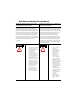
Chapter 7 Interpret Status Indicators (LEDs) For Information On This Topic Refer To Page I/O Status Indicator 7-3 Module (MOD) Status Indicator 7-4 Network (NET) Status Indicator 7-5 The three status indicators on the 1784-PCIDS card provide information about the DeviceNet network and its connections. See Figure 7.1 for an illustration of the status indicators.
7-2 Interpret Status Indicators (LEDs) Figure 7.1 Status Indicators S Allen-Bradley 1784-PCIDS Scanner I/O I/O Status MOD NET Network Status Module Status The tables on pages 7-3 through 7-5 outline the indicator condition and the corresponding status, and explain what each condition means to you.
Interpret Status Indicators (LEDs) 7-3 I/O Status Indicator This bi-color (green/red) LED provides information concerning the states of inputs and/or outputs. Condition Status Indicates off output(s) inactive All Outputs are inactive. input(s) inactive All inputs are inactive. output(s) active One or more outputs are active and under control, and no outputs are faulted. input(s) active One or more inputs are active and producing data, and no inputs are faulted.
7-4 Interpret Status Indicators (LEDs) Module (MOD) Status Indicator This bi-color (green/red) LED provides device status. It indicates whether or not the device has power and is operating properly. Condition Status Indicates off no power No power applied to device. device operational Device is operating in a normal condition. device in standby (device needs commissioning) Device needs commissioning due to configuration missing, incomplete, or incorrect.
Interpret Status Indicators (LEDs) 7-5 Network (NET) Status Indicator This bi-color (green/red) LED indicates the status of the communication link. condition status indicates off not powered, Device is not online. not online The device has not completed the Dup_MAC_ID test yet. The device may not be powered; look at the Module Status LED. flashing green1 online, Device is online, but has no connections in the established state.
7-6 Interpret Status Indicators (LEDs) Notes: Publication 1784-IN004E-EN-P - April 2005
Appendix A Specifications PCI local bus compliant to PCI Rev. 2.2. The 1784-PCIDS card is compatible with 5V and 3.3V PCI slots, 32-bit and 64-bit PCI slots, and PCI-X slots. Attention: The 1784-PCIDS is not compatible with PCI Express and should not be inserted into a PCI Express slot. mechanical form factor Universal PCI 32-bit short card 4.2 in. (10.7 cm) H x 4.72 in.
A-2 Specifications non-operating shock IEC 60068-2-27 (Test Ea, Unpackaged Shock): 50g emissions CISPR 11: Group 1, Class A ESD immunity IEC 61000-4-2: 6kV contact discharges 8kV air discharges radiated RF immunity IEC 61000-4-3: 10V/m with 1kHz sine-wave 80%AM from 80MHz to 2000MHz 10V/m with 200Hz 50% pulse 100%AM at 900MHz 10V/m with 200Hz 50% pulse 100%AM at 1890MHz EFT/B immunity IEC 61000-4-4: +/-2kV at 5kHz on communications ports surge transient immunity IEC 61000-4-5: +/-2kV line-earth
Specifications A-3 wiring category1 2 - on communications ports certifications (when product is marked)2 UR UL Recognized Component Industrial Control Equipment CSA CSA Accepted Component for Process Control Equipment CSA Accepted Component for Process Control Equipment in Class I, Division 2 Group A,B,C,D Hazardous Locations CE European Union 89/336/EEC EMC Directive, compliant with: EN 50082-2; Industrial Immunity EN 61326; Meas./Control/Lab.
A-4 Specifications Notes: Publication 1784-IN004E-EN-P - April 2005
Index Install The Card 2-1 Install the Cards 1-2 Install The Driver In Windows 2000 4-1 In Windows XP 3-1 Interpret Status Indicators Numerics 1784-PCIDS Card Create 5-2 C Change The Scanner Mode 6-5 Chassis Monitor 5-3 Communication on DeviceNet 1-1 Configure The Port 6-2 Configure The Scan List 5-7 Connect A SoftLogix5800 Controller To DeviceNet 5-2 Connect To The Network 2-3 Create 1784-PCIDS Card 5-2 A View 6-3 Create A View 6-3 L LEDs Interpret 7-1 N Network Connect To 2-3 DeviceNet Connect To 2-
2 Index U Update The Driver In Windows 2000 4-4 In Windows XP 3-4 Use The DeviceNet Test Application 6-1 W Write Outputs 6-4 Publication 1784-IN004E-EN-P - April 2005
How Are We Doing? Your comments on our technical publications will help us serve you better in the future. Thank you for taking the time to provide us feedback. You can complete this form and mail it back to us, visit us online at www.ab.com/manuals, or email us at RADocumentComments@ra.rockwell.com Pub. Title/Type DeviceNet Universal PCI Scanner Card Cat. No. 1784-PCIDS Series B Pub. No. 1784-IN004E-EN-P Pub. Date April 2005 Part No.
PLEASE FASTEN HERE (DO NOT STAPLE) Other Comments PLEASE FOLD HERE NO POSTAGE NECESSARY IF MAILED IN THE UNITED STATES BUSINESS REPLY MAIL FIRST-CLASS MAIL PERMIT NO.
Rockwell Automation Support Rockwell Automation provides technical information on the web to assist you in using its products. At http://support.rockwellautomation.com, you can find technical manuals, a knowledge base of FAQs, technical and application notes, sample code and links to software service packs, and a MySupport feature that you can customize to make the best use of these tools.