
User Manual User Manual

Publication DNET-UM003A-EN-P - August 2000
Connect Devices and Commission Nodes 3-15
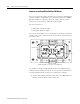
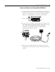
Attach the Module
1. Position the module over the mounted cable base. Align the
three captive screws in the module with the accepting
receptacles in the base.
2. Tighten the screws with a torque of 8 inch-pounds (0.904 NM)
to secure the module to the base.
ArmorBlock MaXum I/O modules are described in the publications:
• 1792D-5.12 through 5.23 ArmorBlock MaXum Installation
Instructions
• 1792-2.1 - ArmorBlock Product Data
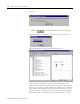
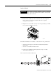
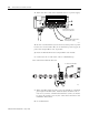
3. Connect the Standard Proximity Switch to input 1 on the
ArmorBlock MaXum I/O.
Your network should look like this:
IMPORTANT
Be certain to properly align the screws to complete
the connections between the module contacts and
the cable contacts.
30704-M
I-0
A-0
I-1
A-1
O-0
O-1
Auxiliary Power
Network Status
Module Status
42036
To the scanner:
T
T