User Manual EtherNet/IP to DeviceNet Linking Device Catalog Number 1788-EN2DNR
Important User Information Read this document and the documents listed in the additional resources section about installation, configuration, and operation of this equipment before you install, configure, operate, or maintain this product. Users are required to familiarize themselves with installation and wiring instructions in addition to requirements of all applicable codes, laws, and standards.
Table of Contents Preface Additional Resources . . . . . . . . . . . . . . . . . . . . . . . . . . . . . . . . . . . . . . . . . . . . . . . 5 Chapter 1 Linking Device Overview About the Linking Device . . . . . . . . . . . . . . . . . . . . . . . . . . . . . . . . . . . . . . . . . . 7 Features . . . . . . . . . . . . . . . . . . . . . . . . . . . . . . . . . . . . . . . . . . . . . . . . . . . . . . . . . . . 8 Linking Device Features . . . . . . . . . . . . . . . . . . . . . . . . . . . . . . . . . .
Table of Contents Chapter 4 USB Cable Connect via USB to the Linking Device . . . . . . . . . . . . . . . . . . . . . . . . . . . . 33 Configure the USB Driver. . . . . . . . . . . . . . . . . . . . . . . . . . . . . . . . . . . . . 34 Chapter 5 SD Card Install or Remove the SD Card . . . . . . . . . . . . . . . . . . . . . . . . . . . . . . . . . . . . Load or Store to the SD Card. . . . . . . . . . . . . . . . . . . . . . . . . . . . . . . . . . . . . . Store to the SD Card. . . . . . . . . . . . . .
Preface Additional Resources These documents contain additional information concerning related products from Rockwell Automation. Resource Description Industrial Automation Wiring and Grounding Guidelines, publication 1770-4.1 Provides general guidelines for installing a Rockwell Automation industrial system. DeviceNet Media Design and Installation Guide, publication DNET-UM072 Provides information about how to design, install and troubleshoot a DeviceNet cable system.
Preface Notes: 6 Rockwell Automation Publication 1788-UM059A-EN-P - August 2014
Chapter 1 Linking Device Overview About the Linking Device The 1788-EN2DNR EtherNet/IP-to-DeviceNet linking device lets you seamlessly connect your information or control-level networks with your device-level network. The linking device provides full DeviceNet master functionality, so you can connect up to 63 DeviceNet slave devices to an Ethernet TCP/IP interface that supports the EtherNet/IP network and an HTTP web server.
Chapter 1 Linking Device Overview Features The 1788-EN2DNR module has the following features. Linking Device Features For Class 0 CIP Safety connections, 5 ms maximum delay from network to network EtherNet/IP Features • The linking device supports these connections: – 32 Class 0 connections (Safety) – 21 Class 1 connections (1 excl.
Chapter 2 Install the Linking Device System Requirements The following hardware and software components are required to use the linking device.
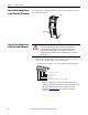
Chapter 2 Install the Linking Device Connect the Linking Device to the EtherNet/IP Network Connect the EtherNet/IP network cable to either of the two RJ45 ports on the front of the linking device. RJ45 Ports Connect the Linking Device to the DeviceNet Network ATTENTION: Do not wire more than two conductors on any single terminal.
Install the Linking Device Chapter 2 2. Connect the power cable to the linking device. The female terminal block connector is provided with the linking device. 1 2 3 Pin No. Description 1 +24 V DC 2 GND 3 PE (Protective Earth) 3. Apply power to the linking device and DeviceNet network.
Chapter 2 Install the Linking Device Switch Data Rate 1 250 kbps 2 500 kbps Other value Data rate selected via RSNetWorx software Set the DeviceNet Node Address and Data Rate by Using RSNetWorx for DeviceNet Software See Set the DeviceNet Node Address and Data Rate on page 20 for information about using RSNetWorx software to set node address and data rate.
Install the Linking Device Chapter 2 Set the Linking Device IP Address by Using DHCP/BOOTP TIP The use of DHCP is the default configuration for the linking device as shipped. When DHCP/BOOTP is enabled and a DHCP or BOOTP server is found, the IP address, subnet mask, and gateway address are automatically configured by the DHCP server, as shown in the following figure. Automatic Configuration Launch a DHCP/BOOTP Server.
Chapter 2 Install the Linking Device The following figure shows a flowchart describing how the IP configuration is determined when the linking device is powered up. IP Configuration Flowchart Start No Rotary Switches = 888? Yes Factory Reset to DHCP Rotary Switches = 000? Yes No LED Indication Admin Mode Operational Mode Rotary Switches 1 - 254? No IP Address: 192.168.1.
Install the Linking Device Chapter 2 Set the Linking Device IP Address by Using RSLinx Software To use RSLinx software to set the IP address of the linking device, follow these steps. 1. Connect to the linking device using a USB cable. 2. From the Communications menu, choose RSWho. 3. Navigate to the USB port. 4. Right-click the linking device and choose Module Configuration. 5. Click the Port Configuration tab. 6.
Chapter 2 Install the Linking Device 8. Configure the port settings. To Then Use the default port speed and duplex settings Leave Auto-negotiate port speed and duplex checked. This setting determines the actual speed and duplex setting. Manually configure your port’s speed and duplex settings Follow these steps. 1. Clear the Auto-negotiate port speed and duplex checkbox. 2. From the Current Port Speed pull-down menu, choose a port speed. 3.
Install the Linking Device Chapter 2 The IP address can be set with the web page only if the linking device already has a valid IP address. One way that you can do this is by using the rotary switch to force the linking device to use the IP address from the switches after you cycle power. Follow these steps to configure the IP address with the web page.
Chapter 2 Install the Linking Device 6. In the Network Configuration dialog box, enter the following values. Description Type IP Address Any valid value. See your system administrator for a valid IP address. Subnet Mask Any valid value. Default Gateway Primary Name Server Secondary Name Server Default Domain Name Host Name 7. Click Apply Changes. 8. Follow the on-dialog box prompts. 9. Cycle power to the linking device. Configure the Driver in RSLinx Software 1.
Chapter 3 Configure the Linking Device RSNetWorx for DeviceNet Software 1. In RSNetWorx for DeviceNet software, choose Network > Online. 2. In the left pane, click the RSLinx Ethernet driver you added previously. See Configure the Driver in RSLinx Software on page 18. 3. In the left pane, click the + next to the 1788-EN2DNR linking device icon. 4. In the left pane, choose DeviceNet, DeviceNet. 5. When asked to upload from the network, click OK to perform a single pass browse.
Chapter 3 Configure the Linking Device Set the DeviceNet Node Address and Data Rate Note that, to be able to set the node address and the data rate from RSNetWorx software, the rotary switches must be set to any value other than 0 - 63. 1. In RSNetWorx for DeviceNet software, choose Tools > Node Commissioning. The Node Commissioning dialog box appears. 2. On the Node Commissioning dialog box, click Browse. The Device Selection dialog box appears. 3.
Configure the Linking Device Chapter 3 4. In the left pane of the dialog box, click the + next to the IP address for the 1788-EN2DNR linking device. 5. In the left pane, click the + next to the DeviceNet network. You see the 1788-EN2DNR linking device in the left pane. 6. Click the 1788-EN2DNR linking device in the left pane. The linking device appears in the right pane. 7. Click OK. 8. If a warning text box asking you if you wish to continue appears, click Yes. 9.
Chapter 3 Configure the Linking Device 10. Click Close. IMPORTANT The linking device automatically restarts the DeviceNet network if a new node address is entered. If the communication rate is changed, you must cycle power to the linking device before the new communication rate takes effect. Note: Data rate changes can cause bus-off errors. Do not change the data rate during live network performance. 11. Restart RSNetWorx for DeviceNet software and go online.
Configure the Linking Device Chapter 3 Enable/Disable Autobaud Autobaud is disabled by default. You can turn it on or off by following the procedure below. 1. In RSNetWorx for DeviceNet software, click the linking device icon. 2. From the Device pull-down menu, choose Class Instance. 3. If a warning dialog box appears, click Yes. The Class Instance Editor dialog box appears. 4. From the Description pull-down menu, choose Set Single Attribute. 5.
Chapter 3 Configure the Linking Device 6. Click Execute. A message in the ‘Data received from device’ box indicates that the execution was completed. IMPORTANT Changes to the autobaud option configuration do not take effect until you cycle power to the linking device. You may also have to cycle power to the slave devices. If the linking device is the only master on the DeviceNet network, do not enable autobaud. Automatic detection requires traffic on the network.
Configure the Linking Device Chapter 3 Configure DeviceNet I/O IMPORTANT Steps 8 and 9 are required only if the linking device is used as an I/O scanner. The linking device can function as a gateway/bridge for explicit messaging and safety I/O routing, even if no I/O is configured. I/O Mapping The DeviceNet I/O configuration defines the format of the Input and Output tables, or the mapping of DeviceNet slaves’ I/O data to the I/O tables.
Chapter 3 Configure the Linking Device 4. Double-click the linking device icon to open the Module Description dialog box. Several tabs appear on the top of the dialog box. 5. Click the Scanlist tab. 6. In the informational dialog box that appears, click Upload. The dialog box shows two columns. On the left is a list of available devices that can be added to the scan list. On the right is a list of devices that are configured in the scan list. 7. Check AutoMap on Add. 8.
Configure the Linking Device Chapter 3 The Input mapping dialog box appears. The top portion of this dialog box lists the devices in the scan list from which the linking device receives input data. The bottom shows the location in the Input table where the data is placed for each device. This shows the format of the Input table of the linking device. This is the format of the input data that is sent to the EtherNet/IP scanner. 10. Click the Output tab. The Output mapping dialog box appears.
Chapter 3 Configure the Linking Device Studio 5000 Environment These procedures explain how to work with the linking device in the Studio 5000® environment. Add the Linking Device to a Logix Designer Application 1. In the Studio 5000 Logix Designer™ application, from the File menu, choose New to create a new project. The New Controller dialog box appears. 2. From the Type pull-down menu, choose the controller type. 3. From the Revision pull-down menu, choose the controller version. 4.
Configure the Linking Device Chapter 3 7. From the Select Module Type dialog box, select 1788-EN2DNR 1788 Ethernet to DeviceNet Linking Device and click Create. The AOP needs to be installed for the linking device to show up in the list. The AOP is available here: https://download.rockwellautomation.com/ esd/download.aspx?downloadid=addonprofiles The New Module dialog box appears. 8. In the Name box, enter a module name. 9.
Chapter 3 Configure the Linking Device 13. If an RSNetWorx for DeviceNet configuration file (filename *.dnt) already exists for the linking device, enter or browse to the appropriate filename. Doing so lets RSNetWorx for DeviceNet software launch directly from the Studio 5000 environment. 14. Click OK. You can now use the linking device as both a bridge and a scanner. 15. Write a user program to use the linking device on the network.
Configure the Linking Device Chapter 3 Assembly Objects and Connections Three Assembly Object instances are accessible from the EtherNet/IP network: input, output and status. The input and output assemblies are linked to the input and output tags created in the Studio 5000 environment. The status assembly provides current status information about the linking device. IMPORTANT With a specific 1788-EN2DNR profile, I/O tags are mapped without an offset.
Chapter 3 Configure the Linking Device Status Assembly The status assembly is a collection of status and diagnostic information for the linking device’s DeviceNet network interface. The information in the assembly is updated once a second. IMPORTANT All information in the status assembly is stored in little endian format. The least significant byte of multibyte values is stored first.
Chapter 4 USB Cable Connect via USB to the Linking Device To use the USB port of the linking device, you must have RSLinx software, version 2.56 or later, installed on your workstation. Use a USB cable to connect your workstation to the USB port of the linking device. With this connection, you can configure the linking device and the DeviceNet network or upgrade the linking device’s firmware, directly from your workstation. ATTENTION: The USB port is intended only for temporary connections.
Chapter 4 USB Cable Configure the USB Driver To configure RSLinx software to use a USB port, you need to configure a USB driver. To configure a USB driver, perform this procedure. 1. Connect the linking device and your workstation by using a USB cable. The Found New Hardware Wizard appears. 2. Click any of the Windows Update connections options and click Next.
USB Cable Chapter 4 4. Click Finish to set up your USB driver. To browse to the linking device in RSLinx software, click the RSWho icon. The RSLinx Workstation organizer appears. The linking device appears under two different drivers, a virtual chassis and the USB port. You can use either driver to browse to the linking device.
Chapter 4 USB Cable Notes: 36 Rockwell Automation Publication 1788-UM059A-EN-P - August 2014
Chapter 5 SD Card Install or Remove the SD Card Complete these steps to install or remove the Secure Digital (SD) card in the linking device. WARNING: When you insert or remove the SD card while power is on, an electrical arc can occur. This could cause an explosion in hazardous location installations. Be sure that power is turned off or the area is nonhazardous before proceeding. IMPORTANT • Verify that the SD card status indicator is off and that the card is not in use before removal.
Chapter 5 SD Card 2. Open the latch situated on the linking device and insert or remove the SD card. 3. Close the SD card latch. Load or Store to the SD Card Using RSLogix 5000, the SD card can be used to load or store the linking device’s configuration. Note that the SD card does not store the scan list created by RSNetworx for DeviceNet. Store to the SD Card To store the linking device’s configuration to the SD card, the SD card must be correctly inserted and unlocked.
SD Card Chapter 5 Load from the SD Card To load the configuration currently on the SD card to the linking device, the inserted SD card can be either locked or unlocked. The image below shows a locked SD card. Clicking Load to Module produces this warning: Clicking Yes loads the configuration stored on the SD card to the linking device. Any configuration currently stored in the linking device is overwritten.
Chapter 5 SD Card Notes: 40 Rockwell Automation Publication 1788-UM059A-EN-P - August 2014
Chapter 6 Diagnostic Web Pages Diagnostic Web Pages— DeviceNet The following sections explain the diagnostic web pages for the DeviceNet network. DeviceNet Status The DeviceNet Status page presents information about the DeviceNet network and general DeviceNet diagnostics. Active Nodes The Active Nodes page indicates which DeviceNet nodes are currently online on the DeviceNet network. Nodes that are listed in the scan list are marked ‘Active’.
Chapter 6 Diagnostic Web Pages Invalid Nodes The Invalid Nodes page indicates which DeviceNet nodes are not the correct device type. If a node’s device type is different than that configured in the scan list, the page displays ‘Invalid’ next to the node’s MAC ID. Note that only nodes configured as slaves to the linking device are updated on this page.
Diagnostic Web Pages Chapter 6 Node Status Codes (Continued) Status Code Description Action 80 Module is in IDLE mode Put controller in RUN mode. Enable RUN bit in module command register. 81 Module is in FAULT mode Check Module Command Register for fault bit set. 82 Error detected in sequence of fragmented I/O messages from device Check scan list table entry for slave device to make sure that input and output data lengths are correct. Check slave device configuration.
Chapter 6 Diagnostic Web Pages Diagnostic Web Pages— Ethernet The following sections explain the diagnostic web pages for Ethernet. Diagnostic Overview General Ethernet information of the linking device, containing the information below: • CPU load • Number of TCP connections • Web server statistics • CIP connections statistics • I/O packet information Network Settings Settings for the Ethernet network are presented here.
Diagnostic Web Pages Chapter 6 Media Counters Port 1/Port 2 Field Description Alignment Errors A frame containing bits that do not total an integral multiple of eight. FCS Errors A frame containing eight bits, at least one of which has been corrupted. Single Collisions The number of outgoing packets that encountered only one collision during transmission. Multiple Collisions The number of outgoing packets that encountered 2...15 collisions during transmission.
Chapter 6 Diagnostic Web Pages Notes: 46 Rockwell Automation Publication 1788-UM059A-EN-P - August 2014
Appendix A Status Indicators Linking Device Indicator Status Description MS (Module Status) Off Green Flashing green Red Flashing red Alternating red/green Orange Repeating one flash orange Repeating two flashes orange Repeating three flashes orange Power off Normal operation The module is not configured Unrecoverable error Recoverable error Power-on self-test (POST) Unrecoverable error: firmware has crashed Unrecoverable error Unrecoverable error Unrecoverable error: firmware is not started SD (SD
Appendix A Status Indicators Notes: 48 Rockwell Automation Publication 1788-UM059A-EN-P - August 2014
Index A active nodes 41 apply power to linking device 11 assembly input 31 output 31 status 32 Autobaud 23 C cable, USB 33 CIP safety connections 8 messages 8 configuration file 30 configuration file, RSNetWorx for DeviceNet 30 configure DeviceNet I/O 25 driver 18 IP address 14 port settings 16 USB driver 34 connectors Phoenix 7 RJ45 7 USB cable 33 D data rate 11, 20 data storage 7 DeviceNet I/O 25 DeviceNet network connect to linking device 10 connectors 7 data storage 7 diagnostic web pages 41 linking d
Index linking device add to Logix Designer application 28 configure port settings 16 configure via Logix Designer application 28 configure via RSNetWorx for DeviceNet software 19 connect to DeviceNet network 10 connect to EtherNet/IP network 10 DeviceNet diagnostic web pages 41 EtherNet/IP diagnostic web pages 44 features 8 install 9 IP configuration 14 overview 7 power 11 register EDS file 18 rotary switches 11, 12 set IP address via DHCP 12 set IP address via rotary switches 12 set IP address via RSLinx
Rockwell Automation Support Rockwell Automation provides technical information on the Web to assist you in using its products. At http://www.rockwellautomation.com/support you can find technical and application notes, sample code, and links to software service packs. You can also visit our Support Center at https://rockwellautomation.custhelp.com/ for software updates, support chats and forums, technical information, FAQs, and to sign up for product notification updates.