CompactBlock LDX I/O Thermocouple Modules 1790D-T4T0, 1790D-4T0, 1790P-T4T0 User Manual
Important User Information Because of the variety of uses for the products described in this publication, those responsible for the application and use of these products must satisfy themselves that all necessary steps have been taken to assure that each application and use meets all performance and safety requirements, including any applicable laws, regulations, codes and standards.
Rockwell Automation Support Before you contact Rockwell Automation for technical assistance, we suggest you please review the troubleshooting information contained in this publication first. If the problem persists, call your local Rockwell Automation representative or contact Rockwell Automation in one of the following ways: Phone Internet United States/Canada 1.440.646.5800 Outside United States/Canada You can access the phone number for your country via the Internet: 1. Go to http://www.ab.com 2.
Table of Contents Important User Information . . . . . . . . . . . . . . . . . . . . . . . . . iii Rockwell Automation Support . . . . . . . . . . . . . . . . . . . . . . . iv Your Questions or Comments on this Manual . . . . . . . . . iv Chapter 1 Overview General Description . . . . . . . . . . . . . . . . . . Thermocouple/mV Inputs and Ranges . . Hardware Features . . . . . . . . . . . . . . . . . . . General Diagnostic Features . . . . . . . . . . System Overview . . . . . . . . . . . . . . . . . . .
vi Chapter 3 Module Data, Status, and Channel Module Memory Map . . . . . . . . . . . . . . . . . . . . . . . . . . . . 3-1 Input Image. . . . . . . . . . . . . . . . . . . . . . . . . . . . . . . . . 3-1 Configuration for DeviceNet Accessing Input Image File Data . . . . . . . . . . . . . . . . . . Input Data File . . . . . . . . . . . . . . . . . . . . . . . . . . . . . . . Input Data Values . . . . . . . . . . . . . . . . . . . . . . . . . . Under-Range Flag Bits (S0 to S3) . . . . . . . . . . . . . . .
vii Appendix B Two’s Complement Binary Numbers Positive Decimal Values . . . . . . . . . . . . . . . . . . . . . . . . . . B-1 Negative Decimal Values . . . . . . . . . . . . . . . . . . . . . . . . . . B-2 Appendix C Thermocouple Descriptions International Temperature Scale of 1990. Type B Thermocouples . . . . . . . . . . . . . Type E Thermocouples . . . . . . . . . . . . . Type J Thermocouples . . . . . . . . . . . . . Type K Thermocouples . . . . . . . . . . . . . Type N Thermocouples. . . . . . . .
viii Publication 1790-UM003A-EN-P - May 2002
Chapter 1 Overview This chapter describes the 1790D-4TO/T4TO (1790P-T4TO) Thermocouple/mV Input module and explains how the module reads thermocouple or millivolt analog input data. Included is: • the module’s hardware and diagnostic features • an overview of system and module operation • compatibility General Description The thermocouple/mV input module supports thermocouple and millivolt signal measurement applications that require up to four channels.
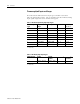
1-2 Overview Thermocouple/mV Inputs and Ranges The table below defines thermocouple types and their associated full-scale temperature ranges. The second table lists the millivolt analog input signal ranges that each channel will support. Table 1.1 Thermocouple Analog Input Signal Types * Thermocouple Type Temperature Range Scaling (Counts) Resolution* Accuracy** (0 to 55°C) B +300 to +1800°C +3000 to +18000 0.1°C ±4.2°C E -270 to +1000°C -2700 to +10000 0.1°C ±2.
Overview Hardware Features 1-3 The thermocouple/mV module contains either a fixed terminal block or a removable D-sub connector, which provides connections for four inputs for any combination of thermocouple and mV input devices. Channels are wired as differential inputs. The illustration below shows the hardware features of the module. Figure 1.
1-4 Overview Internal to the module, Cold Junction Compensation (CJC) sensors are attached to the terminal block to enable accurate readings from each channel. These sensors compensate for offset voltages introduced into the input signal as a result of the cold-junction where the thermocouple wires are connected to the module. General Diagnostic Features Module, network, and channel LEDs help you identify the source of problems that may occur during power-up or during normal channel operation.
Overview 1-5 Module Operation - DeviceNet Example When the module recieves a differential input from an analog device, the module’s circuitry multiplexes the input into an A/D converter. The converter reads the signal and converts it as required for the type of input. The module also continuously samples the CJC sensors and compensates for temperature changes at the terminal block cold junction, between the thermocouple wire and the input channel. See the block diagram below. Figure 1.
1-6 Overview From the readings taken by the converter, the module sends thermocouple or mV data through the microcontroller to the DeviceNet network. The PROFIBUS block diagram is similar. Chapter Summary Publication 1790-UM003A-EN-P In this chapter, you learned about the 1790D-4T0/T4T0 (1790P-T4T0) thermocouple/mV module. See Chapter 2 to learn how to install and wire the module.
Chapter 2 Installation and Wiring Before You Begin This chapter tells you how to: • determine the power requirements for the modules • avoid electrostatic damage • install the module • wire the module’s terminal block Power Requirements 1790D-4T0/T4T0 The module receives system power from the DeviceNet network. An auxiliary field supply provides power for the thermocouple/mV channels. Table 2.
2-2 Installation and Wiring General Considerations The modules are suitable for use in a commercial or light industrial environment when installed in accordance with these instructions. Specifically, this equipment is intended for use in clean, dry environments (Pollution degree 2(1)) and to circuits not exceeding Over Voltage Category II(2) (IEC 60664-1)(3). Hazardous Location Considerations This equipment is suitable for use in Class I, Division 2, Groups A, B, C, D or non-hazardous locations only.
Installation and Wiring 2-3 The following information applies when operating this equipment in hazardous locations: Informations sur l’utilisation de cet équipement en environnements dangereux : Products marked “CL I, DIV 2, GP A, B, C, D” are suitable for use in Class I Division 2 Groups A, B, C, D, Hazardous Locations and nonhazardous locations only. Each product is supplied with markings on the rating nameplate indicating the hazardous location temperature code.
2-4 Installation and Wiring ATTENTION ! Environment and Enclosure This equipment is intended for use in a Pollution Degree 2 industrial environment, in overvoltage Category II applications (as defined in IEC publication 60664-1), at altitudes up to 2000 meters without derating. This equipment is considered Group 1, Class A industrial equipment according to IEC/CISPR Publication 11.
Installation and Wiring ATTENTION ! WARNING ! 2-5 Preventing Electrostatic Discharge This equipment is sensitive to electrostatic discharge, which can cause internal damage and affect normal operation. Follow these guidelines when you handle this equipment: • Touch a grounded object to discharge potential static. • Wear an approved grounding wriststrap. • Do not touch connectors or pins on component boards. • Do not touch circuit components inside the equipment.
2-6 Installation and Wiring Protecting the Circuit Board from Contamination The printed circuit boards of analog modules must be protected from dirt, oil, moisture, and other airborne contaminants. To protect these boards, the system must be installed in an enclosure suitable for the environment. The interior of the enclosure should be kept clean and the enclosure door should be kept closed whenever possible. Installing CompactBlock LDX I/O Follow these steps to install the block: 1.
Installation and Wiring 2-7 Set the Station Address on the 1790P-T4T0 PROFIBUS DP Base Block To set the station address, adjust the switches on the front of the base block. The two switches are most significant digit (MSD) and least significant digit (LSD). The switches can be set between 00 and 99. The rotary switches are read at base block power up only. Example: Node Address is set at 26 43230 Mounting Mount the Base Block You can mount the base block to a panel or DIN rail.
2-8 Installation and Wiring 5. Replace the block on the panel and place a screw through each of the two mounting holes. Tighten the screws until the block is firmly in place. 95 mm 3.74 in k LDX CompactBloc 1790-16BVOX EXPANSION UNIT 41 mm 1.6 in 16 INPUTS-DCPOW Expansion Cover ER 7 7 0 0 43242 DIN Rail Mounting 1. Hook the top slot of the block over the DIN Rail. 2. Pull down on the locking lever while pressing the block against the rail. f Locking Lever 43243 3.
Installation and Wiring 2-9 Connect the DeviceNet Cable to the 1790D-4T0/T4T0 Base Block Follow these procedures when connecting the DeviceNet cable to the base block. The required DeviceNet connector is not supplied with the block you must purchase it separately.
2-10 Installation and Wiring Connect the PROFIBUS DP Terminal Connector to the 1790P-T4T0 Base Block Follow these procedures to connect the PROFIBUS DP terminal connector to the base block. If you connect or disconnect the PROFIBUS cable with power applied to this module or any device on the network, an electrical arc can occur. This could cause an explosion in hazardous location installations. WARNING ! Be sure that power is removed or the area is nonhazardous before proceeding.
Installation and Wiring 2-11 Once you have properly wired the connector, attach it to the base block as shown below. Use the locking screws on the connector to fasten it to the base block. Module Power Connector (underneath module) PROFIBUS Connector Green - GND Black - COM Red - +24V dc 43249 Connect Power to the 1790P-T4T0 Block To apply power to the block, refer to the above illustration.
2-12 Installation and Wiring Field Wiring Connections System Wiring Guidelines Consider the following when wiring your system: General • Route field wiring away from any other wiring and as far as possible from sources of electrical noise, such as motors, transformers, contactors, and ac devices. As a general rule, allow at least 15.2 cm (6 in.) of separation for every 120V of power. • Routing field wiring in a grounded conduit can reduce electrical noise.
Installation and Wiring 2-13 Grounding ATTENTION ! The possibility exists that a grounded or exposed thermocouple can become shorted to a potential greater than that of the thermocouple itself. Due to possible shock hazard, take care when wiring grounded or exposed thermocouples. See Appendix D, Using Thermocouple Junctions. • This product is intended to be mounted to a well-grounded mounting surface such as a metal panel.
2-14 Installation and Wiring Wiring the Module ATTENTION To prevent shock hazard, care should be taken when wiring the module to analog signal sources. Before wiring any module, disconnect power from the system power supply and from any other source to the module. ! After the module is properly installed, follow the wiring procedure below, using the proper thermocouple extension cable, or Belden 8761 for non-thermocouple applications.
Installation and Wiring 2-15 4. At the other end of the cable, cut the drain wire and foil shield back to the cable and apply shrink wrap. 5. Connect the signal wires to the terminal block. Connect the other end of the cable to the analog input device. 6. Repeat steps 1 through 5 for each channel on the module. TIP See Appendix D Using Thermocouple Junctions for additional information on wiring grounded, ungrounded, and exposed thermocouple types.
2-16 Installation and Wiring Cold Junction Compensation To obtain accurate readings from each of the channels, the cold junction temperature (temperature at the module’s terminal junction between the thermocouple wire and the input channel) must be compensated for. Cold junction compensating thermistors have been integrated in the module. Chapter Summary In this chapter, you learned how to install and wire your modules.
Chapter 3 Module Data, Status, and Channel Configuration for DeviceNet After installation of the thermocouple/mV input module, you must configure it for operation, usually using the programming software compatible with the controller (for example, RSLogix 500™ or RSLogix 5000™) or scanner (RSNetWorx for DeviceNet). Once configuration is complete and reflected in ladder logic, you will need to get the module up and running and then verify its operation.
3-2 Module Data, Status, and Channel Configuration for DeviceNet Input Data File The input data table lets you access thermocouple/mV input module read data for use in the control program, via word and bit access. The data table structure is shown in the tables below. Table 3.
Module Data, Status, and Channel Configuration for DeviceNet 3-3 Over-Range Flag Bits (S8 to S11) Over-range bits for channels 0 through 3 are contained in word 4, bits 8-11. When set (1), the over-range flag bit indicates a thermocouple temperature that is greater than the maximum allowed temperature, a resistance input that is greater than the maximum allowed resistance for the module or an open channel is detected.
3-4 Module Data, Status, and Channel Configuration for DeviceNet Filter Frequency The module supports filter selections corresponding to filter frequencies of 10 Hz, 25Hz, 50 Hz, 60 Hz, 100 Hz, 250 Hz, and 500 Hz. Your filter frequency selection is determined by the desired range for the input type, and the required effective resolution, which indicates the number of bits in the input data that do not vary due to noise. Also consider the required module update time when choosing a filter frequency.
Module Data, Status, and Channel Configuration for DeviceNet Channel Step Response 3-5 Another module characteristic determined by filter frequency is channel step response, as shown in the following table. The step response is the time required for the analog input signal to reach 100 percent of its expected final value, given a full-scale step change in the input signal.
3-6 Module Data, Status, and Channel Configuration for DeviceNet Figure 3.2 Frequency Response Graphs 10 Hz Input Filter Frequency 50 Hz Input Filter Frequency 0 –3 dB –20 –20 –40 –40 –60 –60 –80 –80 Gain (dB) Gain (dB) 0 -100 -120 -100 -120 -140 -140 -160 -160 -180 -180 - 200 - 200 0 10 30 20 50 40 60 0 Frequency (Hz) 2.62 Hz –3 dB 50 13.
Module Data, Status, and Channel Configuration for DeviceNet Effective Resolution 3-7 The effective resolution for an input channel depends upon the filter frequency selected for that channel. The table below identifies the number of significant bits used to represent the data for the mV input range for each available filter frequency. The number of significant bits is defined as the number of bits that will have little or no jitter due to noise, and is used in defining the effective resolution. Table 3.
3-8 Module Data, Status, and Channel Configuration for DeviceNet Figure 3.4 Type E Thermocouple Figure 3.
Module Data, Status, and Channel Configuration for DeviceNet 3-9 Figure 3.6 Type K Thermocouple Figure 3.
3-10 Module Data, Status, and Channel Configuration for DeviceNet Figure 3.8 Type S Thermocouple Figure 3.
Module Data, Status, and Channel Configuration for DeviceNet 3-11 Figure 3.10 Type N Thermocouple Cold Junction Compensation When using thermocouples, cold junction compensation (CJC) is required at the termination of the thermocouple wire. A cold junction can be accomplished different ways: • Use the built-in CJC • Enter an estimated temperature • Use an external CJC Entering an estimated temperature may be the least accurate way for CJC compensation. Using external CJC is the most expensive way.
3-12 Module Data, Status, and Channel Configuration for DeviceNet Determining Module Update Time The module update time is defined as the time required for the module to sample and convert the input signals. Module update time is dependent on the number of input channels and the input filter selection. The fastest update time occurs with the 500Hz filter enabled. The following table shows update times for all filter frequencies. Table 3.
Module Data, Status, and Channel Configuration for DeviceNet 3-13 Thermocouple Error The table below summarizes thermocouple error (for more Thermocouple Type information see Appendix C). Table 3.10 Thermocouple Error * Thermocouple Type Useable Range °C Standard Tolerance Error * Special Tolerance Error * B 870 to 1700 ±0.5% ±0.25% E 0 to 900 -200 to 0 ±1.7°C or ±0.5% ±1.7°C or ±1% ±1°C or ±0.4% ±1°C or ±0.5% J 0 to 750 ±2.2°C or ±0.75% ±1.1°C or ±0.4% K 0 to 1250 -200 to 0 ±2.
3-14 Module Data, Status, and Channel Configuration for DeviceNet Total Error As an example, a B Type thermocouple operating at 100°C with 1000 ohms of lead wire, internal CJC and 10Hz filter enabled, in an ambient temperature of 30 to 50°C, is accurate to within: Table 3.12 Example Error Calculation Error Factor From Error Module & Temperature Table 3.9 4.2°C Thermocouple Table 3.10 .005 x 1000°C = 5.0°C Lead Wire Table 3.11 .0004 x 1000°C = 0.
Module Data, Status, and Channel Configuration for DeviceNet Configure DeviceNet Thermocouple/mV Modules Using RSNetWorx 3-15 Following the steps below to configure 1790D-4T0/T4T0 thermocouple/ mV modules. 1. Open RSNetWorx for DeviceNet. 2. Using the selections on the left of the window below, construct you system. (If your network is up, just click on the Online Browse button.
3-16 Module Data, Status, and Channel Configuration for DeviceNet 3. After setting up your system, double-click on the module you want to configure. (If you are online, upload the configuration and existing parameters from the module display.) A window similar to the following appears. Click the device Parameters tab to display the screen in which you can set parameters. Thermocouple/mV modules will have parameters similar to the following.
Module Data, Status, and Channel Configuration for DeviceNet 3-17 Module configuration parameters include Temperature Units/Notch Filter frequency, Thermocouple/mV Input type, Cold Junction Compensation Enable/Manual Offset Value and Autobaud. Select the desired temperature units (in degrees C or F) and notch filter frequency. ALL four channels will be configured identically. Select the thermocouple/ mV input type for each channel from the dropdown list.
3-18 Module Data, Status, and Channel Configuration for DeviceNet Select to Enable or Disable built-in cold junction compensation. If built-in CJC is disabled, you can enter a constant cold junction offset value. The value is always entered in °C. The range is 0 to 70°C (000 to 700). 70°C is entered as 700 (158°F as 700 also). Once module configuration is complete, click either the Download or Apply button and click Yes for the popup question. Then click OK to close the module properties window.
Module Data, Status, and Channel Configuration for DeviceNet 3-19 Thermocouple/mV module parameters may be monitored real time. The most convenient way to monitor module parameters is to: a. Click the Groups checkbox. b. Close the No Group Specified folder c. Open the I/O Input Values and I/O Input Status folders. d. Click the Monitor button. The module parameters are sequentially updated.
3-20 Module Data, Status, and Channel Configuration for DeviceNet Publication 1790-UM003A-EN-P
Chapter 4 Diagnostics and Troubleshooting This chapter describes module troubleshooting, containing information on: • safety considerations when troubleshooting • module vs. channel operation • the module’s diagnostic features • critical vs. non-critical errors • module condition data • contacting Rockwell Automation for assistance Safety Considerations Safety considerations are an important element of proper troubleshooting procedures.
4-2 Diagnostics and Troubleshooting Stand Clear of the Equipment When troubleshooting any system problem, have all personnel remain clear of the equipment. The problem could be intermittent, and sudden unexpected machine motion could occur. Have someone ready to operate an emergency stop switch in case it becomes necessary to shut off power.
Diagnostics and Troubleshooting Power-up Diagnostics 4-3 Power-up diagnostics includes module status and network status. Module Status At module power-up, a series of internal diagnostic tests are performed. These diagnostic tests must be successfully completed. The following table shows module status LED indictor operation. Table 4.
4-4 Diagnostics and Troubleshooting Channel Diagnostics When an input channel is enabled, the module performs a diagnostic check to see that the channel has been properly configured. In addition, the channel is tested on every scan for configuration errors, over-range and under-range, and open-circuit conditions. Over- or Under-Range Detection Whenever the data received at the channel word is out of the defined operating range, an over-range or under-range error is indicated in input data word 4.
Diagnostics and Troubleshooting 4-5 Module Error Definition Table Thermocouple/mV module errors are expressed on a channel basis in input read word 4. The structure of the status data is shown in the following table. Table 4.4 Word Bit Position Word Bit Description 15 14 13 12 11 4 Not Used 10 9 8 S11 S10 S9 S8 7 6 5 Not Used 4 3 2 1 0 S3 S2 S1 S0 Table 4.
4-6 Diagnostics and Troubleshooting Publication 1790-UM003A-EN-P
Appendix A Specifications Environmental Specifications Environmental Specifications Operating Temperature 0 to 55°C (32 to 131°F) IEC 60068-2-1 (Test Ad, Operating Cold), IEC 60068-2-2 (Test Bd, Operating Dry Heat), IEC 60068-2-14 (Test Nb, Operating Thermal Shock) Storage Temperature -40 to 85°C (-40 to 185°F) IEC 60068-2-1 (Test Ab, Un-packaged Non-operating Cold), IEC 60068-2-2 (Test Bb, Un-packaged Non-operating Dry Heat), IEC 60068-2-14 (Test Na, Un-packaged Non-operating Thermal Shock) Relative
A-2 Specifications DeviceNet Specifications PROFIBUS DP Specifications Publication 1790-UM003A-EN-P Specification Value Network protocol I/O Slave messaging: - Poll command - Bit Strobe command - Cyclic command - COS command Network length 500 meters maximum @ 125Kbps 100 meters maximum @ 500Kbps Indicators 1 red/green module status 1 red/green network status Number of nodes 64 maximum - rotary switch type node address setting Communication rate 125Kbps, 250Kbps, 500Kbps - auto baud rate sel
Specifications General Specifications A-3 General Specifications Wiring Category 21 Product Certifications c-UL-us (when product is marked) UR UL Listed for Class I, Division 2 Group A,B,C,D Hazardous Locations, certified for U.S. and Canada UL Recognized Component Industrial Control Equipment CE2 European Union 89/336/EEC EMC Directive, compliant with: EN 61000-6-4; Industrial Emissions EN 50082-2; Industrial Immunity EN61326; Meas./Control/Lab.
A-4 Specifications Thermocouple/mV Specifications Publication 1790-UM003A-EN-P Thermocouple/mV Specifications Inputs per module 4 channel, Thermocouple/mV Input Input Range ±76.50 mV Sensors Supported Sensor Type Degree Counts -7650 to +7650 Voltage 10µV -76.5 to +76.
Appendix B Two’s Complement Binary Numbers The processor memory stores 16-bit binary numbers. Two’s complement binary is used when performing mathematical calculations internal to the processor. Analog input values from the Thermocouple/mV module are returned to the processor in 16-bit two’s complement binary format. For positive numbers, the binary notation and two’s complement binary notation are identical.
B-2 Two’s Complement Binary Numbers Negative Decimal Values In two’s complement notation, the far left position is always 1 for negative values. The equivalent decimal value of the binary number is obtained by subtracting the value of the far left position, 32768, from the sum of the values of the other positions. In the figure below (all positions are 1), the value is 32767 - 32768 = -1.
Appendix C Thermocouple Descriptions The information in this appendix was extracted from the NIST Monograph 175 issued in January 1990, which supersedes the IPTS-68 Monograph 125 issued in March 1974. NIST Monograph 175 is provided by the United States Department of Commerce, National Institute of Standards and Technology.
C-2 Thermocouple Descriptions Studies by Ehringer [39], Walker et al. [25,26], and Glawe and Szaniszlo [24] have demonstrated that thermocouples, in which both legs are platinum-rhodium alloys, are suitable for reliable temperature measurements at high temperatures. Such thermocouples have been shown to offer the following distinct advantages over types R and S thermocouples at high temperatures: (1) improved stability, (2) increased mechanical strength, and (3) higher operating temperatures.
Thermocouple Descriptions C-3 The suggested upper temperature limit of 1700°C given in the ASTM standard [7] for protected type B thermocouples applies to AWG 24 (0.51 mm) wire. This temperature limit applies to thermocouples used in conventional closed-end protecting tubes and it is intended only as a rough guide to the user. It does not apply to thermocouples having compacted mineral oxide insulation.
C-4 Thermocouple Descriptions Type E thermocouples should not be used at high temperatures in sulfurous, reducing, or alternately reducing and oxidizing atmospheres unless suitably protected with protecting tubes. They also should not be used in vacuum (at high temperatures) for extended times because the chromium in the positive thermoelement, a nickel-chromium alloy, vaporizes out of solution and alters the calibration.
Thermocouple Descriptions C-5 The suggested upper temperature limit, 870°C, given in the ASTM standard [7] for protected type E thermocouples applies to AWG 8 (3.25 mm) wire. It decreases to 650°C for AWG 14 (1.63 mm), 540°C for AWG 20 (0.81 mm), 430°C for AWG 24 or 28 (0.51 mm or 0.33 mm), and 370°C for AWG 30 (0.25 mm). These temperature limits apply to thermocouples used in conventional closed-end protecting tubes and they are intended only as a rough guide to the user.
C-6 Thermocouple Descriptions Type J thermocouples are recommended by the ASTM [5] for use in the temperature range from 0°C to 760°C in vacuum, oxidizing, reducing, or inert atmospheres. If used for extended times in air above 500°C, heavy gauge wires are recommended because the oxidation rate is rapid at elevated temperatures. Oxidation normally causes a gradual decrease in the thermoelectric voltage of the thermocouple with time.
Thermocouple Descriptions Type K Thermocouples C-7 This section describes Nickel-Chromium Alloy Versus Nickel-Aluminum Alloy thermocouples, called type K thermocouples. This type is more resistant to oxidation at elevated temperatures than types E, J, or T thermocouples and, consequently, it finds wide application at temperatures above 500°C. The positive thermoelement, KP, which is the same as EP, is an alloy that typically contains about 89 to 90 percent nickel, 9 to about 9.
C-8 Thermocouple Descriptions The ASTM Manual [5] indicates that type K thermocouples should not be used at high temperatures in sulfurous, reducing, or alternately oxidizing and reducing atmospheres unless suitably protected with protecting tubes. They also should not be used in vacuum (at high temperatures) for extended times because the chromium in the positive thermoelement, a nickel-chromium alloy, vaporizes out of solution and alters the calibration.
Thermocouple Descriptions Type N Thermocouples C-9 This section describes Nickel-Chromium-Silicon Alloy Versus Nickel-Silicon-Magnesium Alloy thermocouples, commonly referred to as type N thermocouples. This type is the newest of the letter-designated thermocouples. It offers higher thermoelectric stability in air above 1000°C and better air-oxidation resistance than types E, J, and K thermocouples. The positive thermoelement, NP, is an alloy that typically contains about 84 percent nickel, 14 to 14.
C-10 Thermocouple Descriptions Type N thermocouples, in general, are subject to the same environmental restrictions as types E and K. They are not recommended for use at high temperatures in sulfurous, reducing, or alternately oxidizing and reducing atmospheres unless suitably protected with protecting tubes.
Thermocouple Descriptions C-11 ASTM Standard E230-87 in the 1992 Annual Book of ASTM Standards [7] specifies that the initial calibration tolerances for type N commercial thermocouples be ±2.2°C or ±0.75 percent (whichever is greater) between 0°C and 1250°C. Type N thermocouples can also be supplied to meet special tolerances that are equal to approximately one-half the standard tolerances given above. Tolerances are not specified for type N thermocouples below 0°C.
C-12 Thermocouple Descriptions Type R thermocouples have about a 12 percent larger Seebeck coefficient than do Type S thermocouples over much of the range. Type R thermocouples were not standard interpolating instruments on the IPTS-68 for the 630.74°C to gold freezing-point range. Other than these two points, and remarks regarding history and composition, all of the precautions and restrictions on usage given in the section on type S thermocouples also apply to type R thermocouples.
Thermocouple Descriptions C-13 A reference function for the type S thermocouple, based on the ITS-90 and the SI volt, was determined recently from new data obtained in an international collaborative effort involving eight national laboratories. The results of this international collaboration were reported by Burns et al. [28]. The new function was used to compute the reference table given in this monograph.
C-14 Thermocouple Descriptions McLaren and Murdock [30-33] and Bentley and Jones [34] thoroughly studied the performance of type S thermocouples in the range 0°C to 1100°C. They described how thermally reversible effects, such as quenched-in point defects, mechanical stresses, and preferential oxidation of rhodium in the type SP thermoelement, cause chemical and physical inhomogeneities in the thermocouple and thereby limit its accuracy in this range. They emphasized the important of annealing techniques.
Thermocouple Descriptions C-15 The negative thermoelement, TN or EN, is a copper-nickel alloy known ambiguously as constantan. The word constantan refers to a family of copper-nickel alloys containing anywhere from 45 to 60 percent copper. These alloys also typically contain small percentages of cobalt, manganese and iron, as well as trace impurities of other elements such as carbon, magnesium, silicon, etc.
C-16 Thermocouple Descriptions Type T thermocouples are recommended by the ASTM [5] for use in the temperature range from -200°C to 370°C in vacuum or in oxidizing, reducing or inert atmospheres. The suggested upper temperature limit for continuous service of protected type T thermocouples is set at 370°C for AWG 14 (1.63 mm) thermoelements since type TP thermoelements oxidize rapidly above this temperature.
Thermocouple Descriptions References C-17 [1] Preston-Thomas, H. The International Temperature Scale of 1990 (ITS-90). Metrologia 27, 3-10; 1990. ibid. p. 107. [2] The International Practical Temperature Scale of 1968, Amended Edition of 1975. Metrologia 12, 7-17, 1976. [3] Mangum, B. W.; Furukawa, G. T. Guidelines for realizing the International Temperature Scale of 1990 (ITS-90). Natl. Inst. Stand. Technol. Tech. Note 1265; 1990 August. 190 p. [4] The 1976 Provisional 0.5 to 30 K Temperature Scale.
C-18 Thermocouple Descriptions [14] Potts, J. F. Jr.; McElroy, D. L. The effects of cold working, heat treatment, and oxidation on the thermal emf of nickel-base thermoelements. Herzfeld, C. M.; Brickwedde, F. G.; Dahl, A. I.; Hardy, J. D., ed. Temperature: Its Measurement and Control in Science and Industry; Vol. 3, Part 2; New York: Reinhold Publishing Corp.; 1962. 243-264. [15] Burley, N. A.; Ackland, R. G. The stability of the thermo-emf/ temperature characteristics of nickel-base thermocouples. Jour.
Thermocouple Descriptions C-19 [24] Glawe, G. E.; Szaniszlo, A. J. Long-term drift of some noble- and refractory-metal thermocouples at 1600K in air, argon, and vacuum. Temperature: Its Measurement and Control in Science and Industry; Vol. 4; Plumb, H. H., ed.; Pittsburgh: Instrument Society of America; 1972. 1645-1662. [25] Walker, B. E.; Ewing, C. T.; Miller, R. R. Thermoelectric instability of some noble metal thermocouples at high temperatures. Rev. Sci. Instrum. 33, 1029-1040; 1962. [26] Walker, B.
C-20 Thermocouple Descriptions [33] McLaren, E. H.; Murdock, E. G. Properties of some noble and base metal thermocouples at fixed points in the range 0-1100°C. Temperature: Its Measurement and Control in Science and Industry; Vol. 5; Schooley, J. F., ed.; New York: American Institute of Physics; 1982. 953-975. [34] Bentley, R. E.; Jones, T. P. Inhomogeneities in type S thermocouples when used to 1064°C. High Temperatures- High Pressures 12, 33-45; 1980. [35] Rhys, D. W.; Taimsalu, P.
Thermocouple Descriptions C-21 [46] Burley, N. A.; Hess, R. M.; Howie, C. F. Nicrosil and nisil: new nickel-based thermocouple alloys of ultra-high thermoelectric stability. High Temperatures- High Pressures 12, 403-410; 1980. [47] Burley, N. A.; Cocking, J. L.; Burns, G. W.; Scroger, M. G. The nicrosil versus nisil thermocouple: the influence of magnesium on the thermoelectric stability and oxidation resistance of the alloys. Temperature: Its Measurement and Control in Science and Industry; Vol.
C-22 Thermocouple Descriptions 6; Schooley, J. F., ed.; New York: American Institute of Physics; 1992. 579-584. [57] Bentley, R. E. The new nicrosil-sheathed type N MIMS thermocouple: an assessment of the first production batch. Mater. Australas. 18(6), 16-18; 1986. [58] Bentley, R. E.; Russell, Nicrosil sheathed mineral-insulated type N thermocouple probes for short-term variable-immersion applications to 1100°C. Sensors and Actuators 16, 89-100; 1989. [59] Bentley, R. E.
Appendix D Using Thermocouple Junctions This appendix describes the types of thermocouple junctions available, and explains the trade-offs in using them with the thermocouple/mV analog input module. ATTENTION ! Take care when choosing a thermocouple junction, and connecting it from the environment to the module. If you do not take adequate precautions for a given thermocouple type, the electrical isolation of the module might be compromised.
D-2 Using Thermocouple Junctions The shield input terminals for a grounded junction thermocouple are connected together and then connected to chassis ground. Use of this thermocouple with an electrically conductive sheath removes the thermocouple signal to chassis ground isolation of the module. In addition, if multiple grounded junction thermocouples are used, the module channel-to-channel isolation is removed, since there is no isolation between signal and sheath (sheaths are tied together).
Using Thermocouple Junctions D-3 Measuring Junction Isolated from Sheath Using an Exposed Junction Thermocouple An exposed junction thermocouple uses a measuring junction that does not have a protective metal sheath. A thermocouple with this junction type provides the fastest response time but leaves thermocouple wires unprotected against corrosive or mechanical damage.
D-4 Using Thermocouple Junctions To prevent violation of channel-to-channel isolation: • For multiple exposed junction thermocouples, do not allow the measuring junctions to make direct contact with electrically conductive process material. • Preferably use a single exposed junction thermocouple with multiple ungrounded junction thermocouples. • Consider using all ungrounded junction thermocouples instead of the exposed junction type.
Appendix E Module Configuration for PROFIBUS After installation of the thermocouple/mV module, you must configure it for operation, usually by using the programming software compatible with the controller or scanner. This appendix includes PROFIBUS configuration information. Chapter 3 contains detailed information on module parameters and performance.
E-2 Module Configuration for PROFIBUS If it’s not already installed, add the thermocouple/mV module GSD file from the dropdown menu. Access: 1. Library>Add GSD. 2. Click File>New. If the PROFIBUS devices pane is closed, choose: 3. View>Library to open the pane. If the on-line Browse pane is closed, choose: 4. View>On-line to open the pane. You should now be ready to set up your system. 5. Expand the Master and Slaves folders in the PROFIBUS Device pane.
Module Configuration for PROFIBUS E-3 Choose the Master communication parameters You can add modules to the network by: 1. Selecting slaves from the PROFIBUS Device pane 2. Dragging and dropping them to the network pane Or, if online, by performing a search for slaves See the following screens for an outline of this procedure. First, configure the network search properties. Second, search for slave modules.
E-4 Module Configuration for PROFIBUS Highlight the slave, right click the mouse and select GSD Files>1790P-T4T0.gsd 7. Highlight the slave from the Online Browse pane and drag and drop it to the Network pane. The slave station number should be set. (If you dragged and dropped from the PROFIBUS Device pane, you must set the station number.) Station number should be set Highlight and drag and drop the slave device to the Network pane 8.
Module Configuration for PROFIBUS The 1790P-T4T0 module produces 5 words of data. E-5 The produced 5 words will appear in the processor input data table. 9. Click the Ext. Prms tab. This is where the parameters that can be set for the slave thermocouple/mV module are configured. On this screen, you see all the parameters for the module. These include watchdog time, temperature units, filter frequency, cold junction compensation enable, manual offset and input thermocouple/ mV type.
E-6 Module Configuration for PROFIBUS Select the temperature units (°C or °F). All four channels will be configured identically. Select the filter cutoff frequency desired. All four channels will be configured identically. Select to enable (auto) or disable (manual) built-in cold junction compensation. If built-in CJC is disabled, you can enter a constant cold junction offset value. The value is always entered in °C. The range is 0 to 70°C (000 to 700).
Module Configuration for PROFIBUS E-7 Select the thermocouple/mV input type for each channel from the dropdown list. 10. When configuration is complete, click the OK button to close the module properties screen. Save the Configuration To close the configuration: 1. Choose File>Save As. 2. Specify a file name and location to save your configuration. 3. Click Save. This saves your project as a .pbc (PROFIBUS configuration file). Download the Configuration To download the configuration: 1.
E-8 Module Configuration for PROFIBUS 4. Right click to select Connect from the menu. (Or, choose Edit>Connect). Highlight the Master and then right click to select Connect. You may be prompted with a message indicating a configuration mismatch between what is in the scanner and your current PROFIBUS project. In this case, select Yes to retain your configuration. Any configuration mismatches display for the Master status.
Module Configuration for PROFIBUS E-9 5. Load the configuration to the Master through one of the following methods. • Right click on the Master and select Load Configuration from the menu. Or, • Select the Load configuration icon in the toolbar. If the scanner is online, the following message displays: Card is online. Do you want to load configuration. • Select Yes to load your new configuration.
E-10 Module Configuration for PROFIBUS The Net LED on the thermocouple/mV module should turn solid green as should the Comm LED on the scanner. The connection should report OK. The master should now display: Summary This appendix illustrated how to configure your PROFIBUS thermocouple/mV module with the SST PROFIBUS Configuration tool. For more information, consult your PROFIBUS network documentation, PROFIBUS scanner documentation and network configuration tool documentation.
Glossary The following terms and abbreviations are used throughout this manual. For definitions of terms not listed here refer to Allen-Bradley’s Industrial Automation Glossary, Publication AG-7.1. A/D Converter– Refers to the analog to digital converter inherent to the module. The converter produces a digital value whose magnitude is proportional to the magnitude of an analog input signal. attenuation – The reduction in the magnitude of a signal as it passes through a system.
G-2 effective resolution – The number of bits in a channel configuration word that do not vary due to noise. filter – A device that passes a signal or range of signals and eliminates all others. filter frequency – The user-selectable frequency for a digital filter. full-scale – The magnitude of input over which normal operation is permitted. full-scale range – The difference between the maximum and minimum specified analog input values for a device.
G-3 normal mode rejection – (differential mode rejection) A logarithmic measure, in dB, of a device’s ability to reject noise signals between or among circuit signal conductors. The measurement does not apply to noise signals between the equipment grounding conductor or signal reference structure and the signal conductors.
G-4 Publication 1790-UM003A-EN-P
Index Numerics 1790D-4T0 general description 1-1 hardware features 1-3 power requirements 2-1 1790D-T4T0 general description 1-1 hardware features 1-3 power requirements 2-1 1790P-T4T0 connecting power 2-11 general description 1-1 hardware features 1-3 power requirements 2-1 A A/D definition G-1 A/D Converter 1-5 abbreviations G-1 accuracy CJC Error 3-13 error 3-12 lead wire error 3-13 module error 3-12 temperature error 3-12 thermocouple error 3-13 activating devices when troubleshooting 4-1 addressing 3-
I-2 D data configuration for DeviceNet 3-1 data format 3-3 data word definition G-1 dB definition G-1 decibel. See dB.
I-3 set station address (PROFIBUS) 2-7 mounting 2-7 base block 2-7 connecting DeviceNet cable 2-9 connecting power to PROFIBUS block 2-11 connecting PROFIBUS DP connector 2-10 DIN rail mounting 2-8 panel mounting 2-7 power requirements 2-1 installing CompactBlock LDX I/O 2-6 International Temperature Scale of 1990 C-1 ITS-90. See International Temperature Scale of 1990.
I-4 R register configuration 3-1 resolution definition G-3 S safety circuits 4-2 safety considerations 4-1 activating devices when troubleshooting 4-1 indicator lights 4-1 program alteration 4-2 safety circuits 4-2 stand clear of equipment 4-2 sampling time definition G-3 scan time G-2 selecting a location 2-5 set node address (1790D-4T0/T4T0) 2-6 set station address (PROFIBUS) 2-7 signal types thermocouple 1-2 signal types mV 1-2 specifications A-1 DeviceNet A-2 environmental A-1 general A-3 PROFIBUS DP
I-5 W wire type 2-14 wiring 2-1 guidelines 2-12 modules 2-14 routing considerations 2-5 terminal blocks 2-15 Publication 1790-UM003A-EN-P - May 2002
I-6 Publication 1790-UM003A-EN-P - May 2002
How Are We Doing? Your comments on our technical publications will help us serve you better in the future. Thank you for taking the time to provide us feedback. You can complete this form and mail it back to us, visit us online at www.ab.com/manuals, or email us at RADocumentComments@ra.rockwell.com Pub. Title/Type CompactBlock LDX I/O Thermocouple Modules User Manual Cat. No. 1790D-T4T0, Pub. No. 1790D-4T0, 1790P-T4T0 1790-UM003A-EN-P Pub. Date May 2002 Part No.
PLEASE FASTEN HERE (DO NOT STAPLE) PLEASE FOLD HERE NO POSTAGE NECESSARY IF MAILED IN THE UNITED STATES BUSINESS REPLY MAIL FIRST-CLASS MAIL PERMIT NO.
Publication 1790-UM003A-EN-P - May 2002 2 PN 957657-67 Copyright © 2002 Rockwell Automation. All rights reserved. Printed in the U.S.A.