Installation Instructions CompactBlock I/O for DeviceNet Modules Series D (Cat. No. 1791D-16B0, -16V0, -0V16P, -0B16P, -16B0X, -16V0X, -0B16PX, -0V16PX, -8B8P, -4B0, -4B4P, -0B8P, -8V8P) 1791D CompactBlock™ I/O modules are stand-alone 24V dc Block I/O products that communicate via a DeviceNet™ link. Each DeviceNet node consists of either one base module or one base module coupled with one expansion module. NOTE: The 1791D-4B0 module cannot be expanded.
CompactBlock I/O for DeviceNet Modules Series D Any illustrations, charts, sample programs, and layout examples shown in this publication are intended solely for purposes of example. Since there are many variables and requirements associated with any particular installation, Rockwell Automation does not assume responsibility or liability (to include intellectual property liability) for actual use based upon the examples shown in this publication. Allen-Bradley publication SGI-1.
CompactBlock I/O for DeviceNet Modules Series D 3 Environment and Enclosure This equipment is intended for use in a Pollution Degree 2 industrial environment, in overvoltage Category II applications (as defined in IEC publication 60664-1), at altitudes up to 2000 meters without derating. This equipment is considered Group 1, Class A industrial equipment according to IEC/CISPR Publication 11.
CompactBlock I/O for DeviceNet Modules Series D Installing CompactBlock I/O Follow these steps, to install the 1791D I/O module: 1. Set the Node Address on the Base Module. 2. Mount the Block(s). 3. Connect the Input/Output Wires to the Block. 4. Connect the DeviceNet Cable. 5. Remove the terminal block. 6. Insert the terminal block. 7. Communicate with the 1791D Module. These steps are explained in detail in the following procedures.
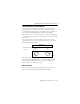
CompactBlock I/O for DeviceNet Modules Series D 5 Set the Node Address on the Base Module Each 1791D base module comes with its internal program set for node address 63. To reset the node address, adjust the switches located behind the door on top of the module. The two switches are most significant digit (MSD) and least significant digit (LSD). The switches can be set between 00 and 63. Use the node adjusting tool provided in the package, or a small bladed screwdriver to rotate the switches.
CompactBlock I/O for DeviceNet Modules Series D Base Module Mounting You can install the CompactBlock base module on a panel or DIN rail. WARNING ! When used in a Class I, Division 2, hazardous location, this equipment must be mounted in a suitable enclosure with proper wiring method that complies with the governing electrical codes. Panel Mounting 1. Place the module against the panel where you want to mount it. 2. Drill holes in the panel that are aligned with mounting holes on the module. 3.
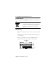
CompactBlock I/O for DeviceNet Modules Series D 7 DIN Rail Mounting 1. Hook top of slot over the DIN Rail. 2. Pull down on the locking lever while pressing the block against the rail. Locking Lever 90358 3. Push up on the locking lever to secure the block to the rail when block is flush against the rail. Connecting an Expansion Module to a Base Module ATTENTION ! IMPORTANT Expansion blocks should not be installed when power is applied to the base.
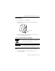
CompactBlock I/O for DeviceNet Modules Series D 2. Position the expansion block with the proper spacing. See the illustration below. Base Module 141 mm 5.55 in 25 mm 1 in Expansion Module 104 mm 4.09 in 41 mm 1.6 in Expansion 41 mm 1.6 in 30358 3. Mount expansion module using panel or DIN rail mounting, as described in the previous section. 4. Plug the expansion cable into both the base and expansion modules.
CompactBlock I/O for DeviceNet Modules Series D 9 Connect the Input/Output Wires to the Block Two sets of VDC+ and GND power pins are located on each terminal (one for each bank of 8 points) except on the 1791D-4B0, -4B4P, and -0B8P modules. The following figures show the wiring information for both sinking and sourcing wiring. Refer to the following table for the proper cable to use for your application. WARNING Use supply wires suitable for 30°C above surrounding ambient.
CompactBlock I/O for DeviceNet Modules Series D Output Wiring Diagram for 1791D-0V16P and 1791D-0V16PX Modules OUT 0 VDC OUT 2 GND OUT 1 - Load OUT 4 OUT 3 OUT 6 OUT 5 VDC OUT 8 GND OUT 7 Not Used OUT 10 OUT 12 OUT 14 OUT 9 OUT 11 OUT 13 OUT 15 41726 + Input Wiring Diagram for 1791D-16V0 and 1791D-16V0X Modules VDC IN 0 GND IN 2 IN 1 IN 4 IN 3 IN 6 IN 5 VDC IN 7 IN 8 GND IN 10 IN 9 IN 12 IN 11 Not Used IN 14 IN 13 IN 15 + 41670 Input Wiring Diagram for 1791D-16B0
CompactBlock I/O for DeviceNet Modules Series D 11 Wiring Diagram for the 1791D-8B8P Module VDC IN 0 GND IN 2 IN 1 IN 4 IN 3 IN 6 IN 5 VDC IN 7 OUT 0 GND OUT 2 OUT 1 OUT 4 OUT 3 Not Used OUT 6 OUT 5 OUT 7 + - Load + - 41672 Wiring Diagram for the 1791D-4B0 Module VDC IN 0 GND GND IN 1 Not Used VDC Not Used GND Not Used VDC IN 2 Not Used GND IN 3 Not Used VDC Not Used GND Not Used VDC + Typical PNP 3-wire sensor + - 42343 - Wiring Diagram for the 1791D-4B4P
CompactBlock I/O for DeviceNet Modules Series D Wiring Diagram for the 1791D-0B8P Module VDC OUT 0 GND GND OUT 1 OUT 2 GND GND OUT 3 VDC GND OUT 4 GND OUT 5 GND OUT 6 GND Not Used GND OUT 7 GND Load + 42345 - Wiring Diagram for the 1791D-8V8P Module VDC IN 0 GND IN 2 IN 1 IN 4 IN 3 IN 6 IN 5 VDC IN 7 OUT 0 GND OUT 2 OUT 1 OUT 4 OUT 3 OUT 6 OUT 5 Not Used OUT 7 Load + - - + 42346 Connect the DeviceNet Cable Refer to the following information when connec
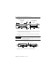
CompactBlock I/O for DeviceNet Modules Series D 13 1. Connect the DeviceNet cable (drop line) to the unsealed DeviceNet terminal connector as shown below. 30361 2. Connect the terminal connector to the Block. Use the side screws on the terminal connector to fasten it to the Block. DeviceNet cable connections must match the color bars on the blocks. Refer to the table below.
CompactBlock I/O for DeviceNet Modules Series D Remove the Terminal Block Follow the directions below to remove the CompactBlock terminal block. WARNING ! When you connect or disconnect the Removable Terminal Block (RTB) with field side power applied, an electrical arc can occur. This could cause an explosion in hazardous location installations. 1. Unscrew the two retaining screws on the side of the terminal block. 2. Lift the terminal block out of the base.
CompactBlock I/O for DeviceNet Modules Series D 15 Insert the Terminal Block To insert the CompactBlock terminal block. 1. Insert the terminal block by aligning it and pushing it back until it rests against the back of the module. 2. Tighten the screws on each side of the terminal block until the terminal block is firmly in place. Communicate With the 1791D Module Determine the Baud Rate for Your DeviceNet Connection All 1791D CompactBlock I/O for DeviceNet modules contain the autobaud feature.
CompactBlock I/O for DeviceNet Modules Series D The module produces 1 byte for every 8 inputs. Similarly, the module consumes 1 byte for every 8 outputs. When an expansion module is connected, an additional byte will be returned indicating the health of the expansion module. When installing an expansion module, refer to the table below to see how many bytes are produced and consumed by the modules.
CompactBlock I/O for DeviceNet Modules Series D 17 Digital Expander Base Expansion I/O Points Produced (input bytes) Consumed (output bytes) 16 output 16 output 32 out 1 4 8 in / 8 out 16 input 24 in /8 out 4 1 Digital Expander Base Expansion I/O Points Produced (input bytes) Consumed (output bytes) 8 in / 8 out 16 output 8 in / 24 out 2 3 4 in / 4 out 16 input 20 in / 4 out 3 1 4 in / 4 out 16 output 4 in / 20 out 1 3 8 out 16 input 16 in / 8 out 3 1 8 out 16 output
CompactBlock I/O for DeviceNet Modules Series D The table below is an example of the word/bit definitions for an 8 in/ 8 out combination module that uses a 16 input expansion module.
CompactBlock I/O for DeviceNet Modules Series D 19 Troubleshoot with the Indicators The 1791D I/O module has the following indicators: • Mod/Net status indicator - base only • Logic status indicator - base only • I/O status indicators - base and expansion Mod/Net Status Indicator Indication: Status: Off No power or auto bauding Flashing Green/Off On line but not connected Solid Green On line, link OK, connected Flashing Red Recoverable fault - (expansion module fault or module configuration error) I
CompactBlock I/O for DeviceNet Modules Series D I/O Status Indicators Function: LED Color: Module Illumination: Condition: Outputs Each output: Yellow None Yellow Output not energized Output energized Inputs Each Input: Yellow None Yellow No valid input Valid input Specifications Sinking or Sourcing Input Specifications Inputs per block groups of 4 or 8 Off-state Voltage 5V dc maximum On-state Voltage 30V dc @ 40°C maximum 25V dc @ 60°C maximum 10V dc minimum Off-state Current 1.
CompactBlock I/O for DeviceNet Modules Series D 21 General Specifications Communication Rate Thick Cable Flat Media Isolation Auxiliary I/O power to DeviceNet I/O group-to-group I/O group-to-DeviceNet DeviceNet Power Voltage Current 125Kbps @ 500m (1600ft) 250Kbps @ 200m (600ft) 500Kbps @ 100m (330ft) 125Kbps @ 420m (1230ft) 250Kbps @ 200m (490ft) 500Kbps @ 75m (245ft) 500V ac/60s 500V ac/60s 500V ac/60s 11 - 25V dc 200mA maximum (with expansion) (for the 1791D-4B0, 150mA) Expansion Power Voltage Curren
CompactBlock I/O for DeviceNet Modules Series D General Specifications Relative Humidity IEC 60068-2-30 (Test Db, Un-packaged Non-operating Damp Heat): 5-95% non-condensing Shock IEC60068-2-27 (Test Ea, Unpackaged shock): Operating 30g Non-operating 50g Emissions CISPR 11: Group 1, Class A Vibration IEC60068-2-6 (Test Fc, Operating): 5g @ 10-500Hz Conductors Wire Size Category 14 gauge (2mm2) stranded maximum 3/64 inch insulation maximum 21, 2 ESD Immunity IEC 61000-4-2: 6kV contact discharg
CompactBlock I/O for DeviceNet Modules Series D 23 General Specifications (continued) Certifications: (when product is marked) UL UL UL Listed Industrial Control Equipment UL Listed for Class I, Division 2 Group A, B, C, D Hazardous Locations c-UL-us UL Listed Industrial Control Equipment, certified for US and Canada c-UL-us UL Listed for Class I, Division 2 Group A,B,C,D Hazardous Locations, certified for U.S.
CompactBlock I/O for DeviceNet Modules Series D North American Hazardous Location Approval The following information applies when operating this equipment in hazardous locations: Informations sur l’utilisation de cet équipement en environnements dangereux : Products marked “CL I, DIV 2, GP A, B, C, D” are suitable for use in Class I Division 2 Groups A, B, C, D, Hazardous Locations and nonhazardous locations only.
CompactBlock I/O for DeviceNet Modules Series D 25 This product has been tested at an Open DeviceNet Vendor Association, Inc. (ODVA) authorized independent test laboratory and found to comply with ODVA Conformance Test. Please contact the ODVA website (http://www.odva.org) for listing of products tested by ODVA independent test labs for further details.
CompactBlock I/O for DeviceNet Modules Series D Notes: Publication 1791D-IN003A-EN-P - June 2003
CompactBlock I/O for DeviceNet Modules Series D 27 CompactBlock and DeviceNetManager are trademarks of Rockwell Automation, Inc. DeviceNet is a trademark of Open DeviceNet Vendor Association. RSNetWorx for DeviceNet is a trademark of Rockwell Software, Inc.
Rockwell Automation Support Rockwell Automation provides technical information on the web to assist you in using our products. At http://support.rockwellautomation.com, you can find technical manuals, a knowledge base of FAQs, technical and application notes, sample code and links to software service packs, and a MySupport feature that you can customize to make the best use of these tools.