
Manual

CompactBlock I/O for DeviceNet Modules Series D 9
Publication
1791D-IN003A-EN-P - June 2003
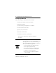
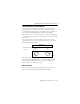
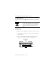
Connect the Input/Output Wires to the Block
Two sets of VDC+ and GND power pins are located on each terminal
(one for each bank of 8 points) except on the 1791D-4B0, -4B4P, and
-0B8P modules. The following figures show the wiring information
for both sinking and sourcing wiring. Refer to the following table for
the proper cable to use for your application.
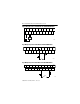
Output Wiring Diagram for 1791D-0B16P and 1791D-0B16PX Modules
!
WARNING
Use supply wires suitable for 30°C above
surrounding ambient.
Use Cable type
Input and output wiring
Up to 14AWG (2mm
2
) stranded (Cu) with 3/64 inch insulation
V
DC
GND
OUT 0 OUT 2
+
OUT 8OUT 6
OUT 1 OUT 3
OUT 4
OUT 5 OUT 7
OUT 10
OUT 9
OUT 12 OUT 14
OUT 11 OUT 15OUT 13
V
DC
GND
-
Load
Not
Used
41669