Installation Instructions ArmorBlock MaXum 16 Input Module with Complete Diagnostics (Cat. No. 1792D-16BVT0CD) 30723-M This ArmorBlock MaXum I/O module (Cat. No. 1792D-16BVT0CD) is a stand-alone 24V dc I/O product which communicates via a DeviceNet network. The sealed housing of this module requires no enclosure. This model has 16 inputs accessed through Y splitter cables. Inputs are 24V dc and are software selectable for PNP (sourcing) or NPN (sinking) devices. The default is sinking.
ArmorBlock MaXum 16 Input Module with Complete Diagnostics Important User Information Because of the variety of uses for the products described in this publication, those responsible for the application and use of these products must satisfy themselves that all necessary steps have been taken to assure that each application and use meets all performance and safety requirements, including any applicable laws, regulations, codes and standards.
ArmorBlock MaXum 16 Input Module with Complete Diagnostics ATTENTION ! WARNING ! IMPORTANT 3 Identifies information about practices or circumstances that can lead to personal injury or death, property damage, or economic loss. Identifies information about practices or circumstances that can cause an explosion in a hazardous environment, which may lead to personal injury or death, property damage, or economic loss.
ArmorBlock MaXum 16 Input Module with Complete Diagnostics Environment and Enclosure This equipment is intended for use in a Pollution Degree 2 industrial environment, in overvoltage Category II applications (as defined in IEC publication 60664-1), at altitudes up to 2000 meters without derating. This equipment is considered Group 1, Class A industrial equipment according to IEC/CISPR Publication 11.
ArmorBlock MaXum 16 Input Module with Complete Diagnostics 5 Install Your ArmorBlock MaXum I/O Module To install the module: • Set the node address • Mount the module to the cable base • Connect the cord sets • Communicate with the module Preventing Electrostatic Discharge This equipment is sensitive to electrostatic discharge, which can cause internal damage and affect normal operation.
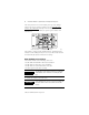
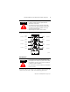
ArmorBlock MaXum 16 Input Module with Complete Diagnostics The rotary switches are read at module power up only. Settings between 64 and 99 cause the module to use the last valid node address stored internally. Example: The last setting was 40. If a change is made to 68, and then you power up, the address will default to 40. Example: Node address is set at 62 (see small black dots). 30703 The module is equipped with AutoBaud detect.
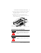
ArmorBlock MaXum 16 Input Module with Complete Diagnostics 7 1. Position the module over the mounted cable base. Align the three captive screws in the module with the accepting receptacles in the base. 2. Tighten the screws to secure the module to the base. Note: Dimensions change according to the cable base and module combination used. 2.7 (68.6) 6.85 (174mm) Align the screws to properly assemble the module to the base. 1.9 (48.26) Cable Base 1792D-CBFM is used for this example.
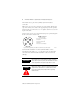
ArmorBlock MaXum 16 Input Module with Complete Diagnostics This module uses 5 pole micro (12mm) style PCB mounted connectors. Eight micro caps cover the connectors on your module. Remove the caps and connect your cables to the appropriate ports. This product has two inputs per connector. Use a “Y” splitter cable for access to all input connections. Use the micro caps to cover and seal unused ports. A pinout diagram for the connectors is shown next.
ArmorBlock MaXum 16 Input Module with Complete Diagnostics ATTENTION ! 9 • Make sure all connectors and caps are securely tightened to properly seal the connections against leaks and maintain IP67 requirements. • For maximum noise immunity, input and output cable return wires must be properly terminated. When inputs and outputs are connected in loopback, return wires should be connected together. • I/O cable length should be less than 30 meters. Input connectors for this module are shown below.
ArmorBlock MaXum 16 Input Module with Complete Diagnostics • 1792D-IN009 ArmorBlock MaXum Cable Base Installation Guide • DN-6.7.2 DeviceNet Cable Planning and Installation Manual Communicate With Your ArmorBlock MaXum Module This ArmorBlock module’s I/O is exchanged with the master through a polled, change-of-state, or cyclic connection.
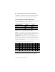
ArmorBlock MaXum 16 Input Module with Complete Diagnostics 11 Byte Bit Description Produced 0 00-07 Input status bits: When the bit is set (1), the input is on. Bit 00 = input 0, bit 01= input 1, bit 02 = input 2, bit 03 = input 3, bit 04 = input 4, bit 05 = input 5, bit 06 = input 6, bit 07 = input 7. Produced 1 00-07 Input status bits: Bit 00 = input 8, bit 01= input 9, bit 02 = input 10, bit 03 = input 11, bit 04 = input 12, bit 05 = input 13, bit 06 = input 14, bit 07 = input 15.
ArmorBlock MaXum 16 Input Module with Complete Diagnostics The DeviceNet Network uses advanced network technology, producer/consumer communication, to increase network functionality and throughput. Visit our website at http://www.ab.com/networks for producer/consumer technology information and updates.
ArmorBlock MaXum 16 Input Module with Complete Diagnostics 13 Net/Mod Status Indicator Indicator Status Solid Red Unrecoverable fault Communication failure - duplicate node address present or incorrect baud rate Green to Red to Off At powerup only - LED test The following table describes logic status indicators.
ArmorBlock MaXum 16 Input Module with Complete Diagnostics 16 Input Module - Cat. No. 1792D-16BVTOCD Off-state Voltage - Sourcing 25V dc (SSV -5)V dc Off-state Current 1.5mA - Off-Wire Sense Current 0.
ArmorBlock MaXum 16 Input Module with Complete Diagnostics 15 16 Input Module - Cat. No. 1792D-16BVTOCD General Specifications (cont.) EFT/B Immunity IEC 61000-4-4: ±4kV at 2.5kHz on signal ports ±4kV at 2.
Hazardous Location Approval The following information applies when operating this equipment in hazardous locations: Informations sur l’utilisation de cet équipement en environnements dangereux : Products marked “CL I, DIV 2, GP A, B, C, D” are suitable for use in Class I Division 2 Groups A, B, C, D, Hazardous Locations and nonhazardous locations only. Each product is supplied with markings on the rating nameplate indicating the hazardous location temperature code.