
Manual
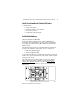
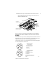
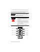
Table Of Contents
- ArmorBlock MaXum 4 Input / 4 Output Module with 8 Connectors, Series B
- Package Contents
- European Union Directive Compliance
- Install Your ArmorBlock MaXum I/O Module
- Set the Node Address
- Install the Module
- Connect the Input / Output Cord Sets to the MaXum Module
- Output Power and DeviceNet Cables
- Communicate With Your ArmorBlock MaXum I/O Module
- Troubleshoot with the Indicators
- Hazardous Location Approval
- Back Cover
ArmorBlock MaXum 4 Input / 4 Output Module with 8 Connectors, Series B 3
Publication 1792D-IN050A-EN-P - February 2001
Install Your ArmorBlock MaXum I/O Module
To install module:
• Set the node address
• Mount the module to the cable base
• Connect the cord sets
• Communicate with the module
Set the Node Address
Valid node addresses are 00 to 63.
Set the node address using the rotary switches, RSNetWorx for
DeviceNet, DeviceNetManager, or other software configuration
tool. Setting the switches between 64 to 99 lets the software have
address control.
Each module is shipped set for node address 63. The switches are
located on the underside of the module. The two switches are:
• MSD (most significant digit)
• LSD (least significant digit)
To reset the node address, use a small blade screwdriver to rotate the
switches. Line up the small black dot on the switch with the number
setting you wish to use.
The rotary switches are read at module power up only. Settings
between 64 and 99 cause the module to use the last valid node
address stored internally. Example: The last setting was 40. If a
change is made to 68, and then you power up, the address will
default to 40.
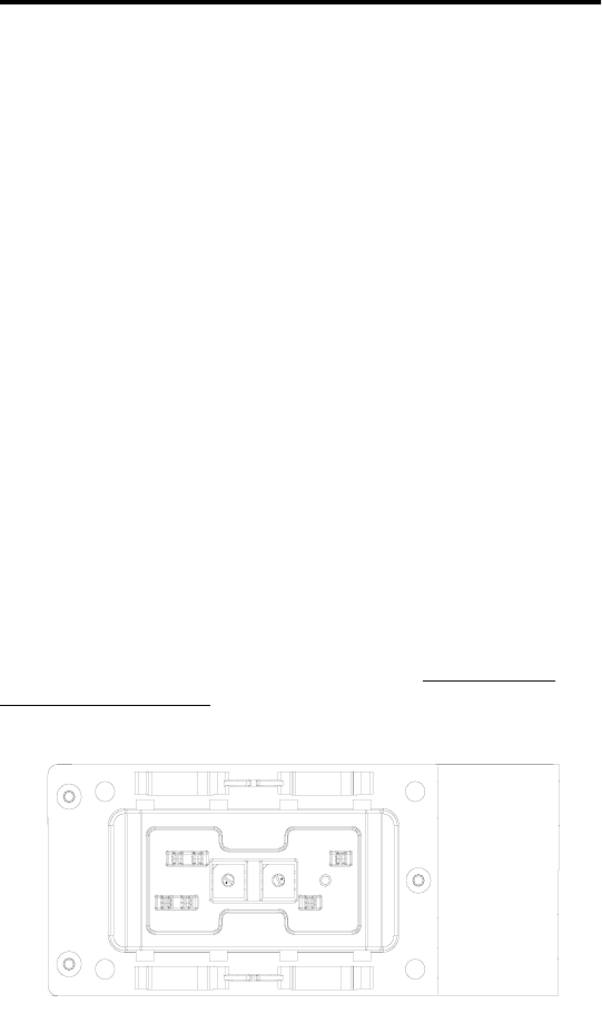
NODE ADDRESS
(00-63 PGM)
LSDMSD
0
1
2
3
4
5
8
9
7
6
0
1
2
3
4
5
8
9
7
6
Bottom View of Module
41462
Example: Node Address is set at 62, see small black dots.