
Manual
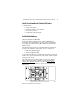
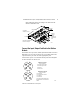
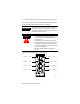
Table Of Contents
- ArmorBlock MaXum 4 Input / 4 Output Module with 8 Connectors, Series B
- Package Contents
- European Union Directive Compliance
- Install Your ArmorBlock MaXum I/O Module
- Set the Node Address
- Install the Module
- Connect the Input / Output Cord Sets to the MaXum Module
- Output Power and DeviceNet Cables
- Communicate With Your ArmorBlock MaXum I/O Module
- Troubleshoot with the Indicators
- Hazardous Location Approval
- Back Cover
6 ArmorBlock MaXum 4 Input / 4 Output Module with 8 Connectors, Series B
Publication 1792D-IN050A-EN-P - February 2001
Please refer to publication 889-CP001A-EN-P and 889-TD001A-EN-P
for Rockwell Automation cables and cord sets offerings.
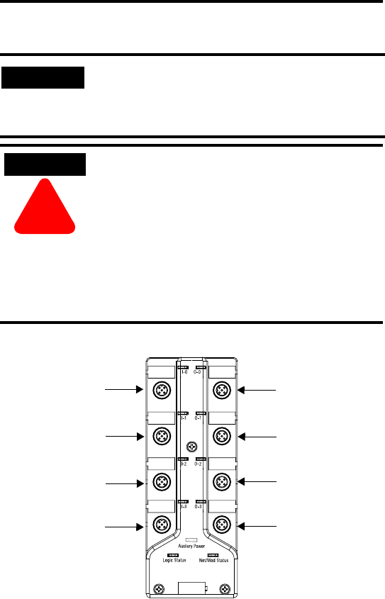
I/O connectors for this module are shown below.
IMPORTANT
If the devices (sensors) connected to the input
connections require Class 2 power to operate, the
DeviceNet connections of this equipment must be
powered by a Class 2 source.
ATTENTION
ÿ
• Make sure all connectors and caps are
securely tightened to properly seal the
connections against leaks and maintain IP67
requirements.
• For maximum noise immunity, input and
output cable return wires must be properly
terminated. When inputs and outputs are
connected in loopback, return wires should
be connected together.
• I/O cable length should be less than 30
meters.
42760
Input 0
Input 1
Input 2
Input 3
Output 0
Output 1
Output 2
Output 3
Connector A
Connector B
Connector C
Connector D
Connector E
Connector F
Connector G
Connector H