
Manual
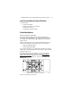
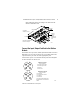
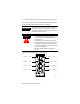
Table Of Contents
- ArmorBlock MaXum 4 Input / 4 Output Module with 8 Connectors, Series B
- Package Contents
- European Union Directive Compliance
- Install Your ArmorBlock MaXum I/O Module
- Set the Node Address
- Install the Module
- Connect the Input / Output Cord Sets to the MaXum Module
- Output Power and DeviceNet Cables
- Communicate With Your ArmorBlock MaXum I/O Module
- Troubleshoot with the Indicators
- Hazardous Location Approval
- Back Cover
ArmorBlock MaXum 4 Input / 4 Output Module with 8 Connectors, Series B 9
Publication 1792D-IN050A-EN-P - February 2001
Troubleshoot with the Indicators
This module has the following indicators:
• Network and Module status indicator
• Logic status indicator
• Auxiliary Power indicator
• Individual I/O status indicators for inputs 0 through 3 and
outputs 0 through 3.
The following table describes network and module status indicators.
Net/Mod Status Indicator
Indicator Status
Off No power or auto bauding
Flashing Green/Off On line but not connected
Solid Green On line, link OK, connected
Flashing Red Recoverable fault - module configuration error
I/O connection fault - one or more I/O connections in the timed-out
state
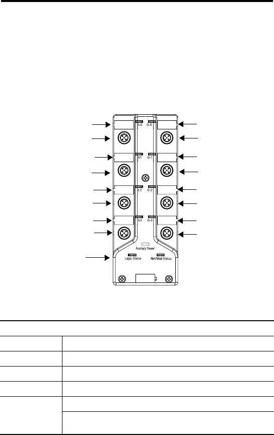
42760
Point indicator for input 0
Module Status
Indicators
Connector A
Connector B
Connector C
Connector D
Connector E
Connector F
Connector G
Connector H
Point indicator for input 1
Point indicator for input 2
Point indicator for input 3
Point indicator for output 3
Point indicator for output 2
Point indicator for output 1
Point indicator for output 0
LED Assignments
Information on connectors
A through H can be found
in the table on page 8.