User Manual FLEX I/O Dual Port EtherNet/IP Adapter Modules Catalog Numbers 1794-AENTR, 1794-AENTRXT
Important User Information Solid-state equipment has operational characteristics differing from those of electromechanical equipment. Safety Guidelines for the Application, Installation and Maintenance of Solid State Controls (publication SGI-1.1 available from your local Rockwell Automation sales office or online at http://www.rockwellautomation.com/literature/) describes some important differences between solid-state equipment and hard-wired electromechanical devices.
Preface Read this preface to familiarize yourself with the rest of the manual. It provides information concerning: • • • • Who Should Use this Manual who should use this manual the purpose of this manual related documentation conventions used in this manual This manual is intended for control engineers and technicians who are installing, configuring, and maintaining a redundant EtherNet/IP control system that communicates with FLEX I/O through a 1794-AENTR or 1794-AENTRXT adapter.
iv Preface Related Documentation The following documents contain additional information concerning Rockwell Automation products. Resource Description FLEX I/O Selection Guide, publication 1794-SG002 A description and overview of the 1794 series FLEX I/O, FLEX I/O XT and FLEX Ex modules and compatible control platforms. FLEX I/O Dual Port EtherNet/IP Adapter Modules, publication 1794-IN131 Information on how to install the FLEX I/O redundant EtherNet/IP adapter modules Catalog No.
Table of Contents Preface Who Should Use this Manual . . . . . . . . . . . . . . . . . . . . . . . . . . . . . . . . . . . . . . iii Purpose of this Manual . . . . . . . . . . . . . . . . . . . . . . . . . . . . . . . . . . . . . . . . . . . . iii Related Documentation. . . . . . . . . . . . . . . . . . . . . . . . . . . . . . . . . . . . . . . . iv Common Techniques Used in this Manual . . . . . . . . . . . . . . . . . . . . . . . . . .
vi Table of Contents Chapter 4 Rack Optimized Discrete I/O Overview . . . . . . . . . . . . . . . . . . . . . . . . . . . . . . . . . . . . . . . . . . . . . . . . . . . . . . . . Set Up the Hardware . . . . . . . . . . . . . . . . . . . . . . . . . . . . . . . . . . . . . . . . . . . . . Create the Example Application . . . . . . . . . . . . . . . . . . . . . . . . . . . . . . . . . . . Configure the I/O. . . . . . . . . . . . . . . . . . . . . . . . . . . . . . . . . . . . . . . . . . . . . . . .
Table of Contents Work with the Home Page . . . . . . . . . . . . . . . . . . . . . . . . . . . . . . . . . . . . . . . . Work with the Diagnostics Pages . . . . . . . . . . . . . . . . . . . . . . . . . . . . . . . . . . Use the Diagnostic Overview Page . . . . . . . . . . . . . . . . . . . . . . . . . . . . . Use the Network Settings Page . . . . . . . . . . . . . . . . . . . . . . . . . . . . . . . . Use the Ethernet Statistics Page . . . . . . . . . . . . . . . . . . . . . . . . . . . . . . . .
viii Table of Contents Notes: Publication 1794-UM066A-EN-P - February 2012
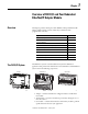
Chapter 1 Overview of FLEX I/O and Your Redundant EtherNet/IP Adapter Module Overview This chapter provides a description of the FLEX I/O dual port EtherNet/IP adapter modules and an overview of how they communicate with programmable controllers.
2 Overview of FLEX I/O and Your Redundant EtherNet/IP Adapter Module The FLEX system consists of an adapter module, terminal base unit, DIN rail, power supply, and adapter cabling components. You can use up to 8 terminal bases per adapter module. For detailed instructions on how to set up and install your module, refer to the topic, Install Your FLEX I/O Adapter on page 7.
Overview of FLEX I/O and Your Redundant EtherNet/IP Adapter Module What the Adapter Does 3 The 1794-AENTR and 1794-AENTRXT adapters perform two primary tasks: • Control of real time I/O data (implicit messaging). The adapter serves as a bridge between I/O modules and the network. L 5 5 7 2 E N 2 T R EtherNet/IP network A E N T R FLEX I/O E N ControlLogix 2 I/O T R Other network devices • Support of messaging data for configuration and programming information(explicit messaging).
4 Overview of FLEX I/O and Your Redundant EtherNet/IP Adapter Module The controller can also produce data for other controllers to consume. The produced and consumed data is accessible by multiple controllers over the EtherNet/IP network. This data exchange conforms to the producer/consumer model. Specifying the Requested Packet Interval (RPI) The RPI is the update rate specified for a particular piece of data on the network.
Overview of FLEX I/O and Your Redundant EtherNet/IP Adapter Module 5 the 8 I/O modules. If you use a rack-optimized connection to transfer the data, you only need a single connection – the connection to the adapter. IMPORTANT Although rack optimized connections offer an efficient way to use resources, there are a few limitations on their use: • You can only use rack optimized connections to send data to and from discrete I/O modules. Analog I/O requires direct connections.
6 Overview of FLEX I/O and Your Redundant EtherNet/IP Adapter Module Notes: Publication 1794-UM066A-EN-P - February 2012
Chapter 2 Install Your FLEX I/O Adapter Overview Module Components This chapter describes how to physically install the 1794-AENTR or 1794-AENTRXT adapter on the DIN rail and connect it to the EtherNet/IP network. The following table lists where to find specific information.
8 Install Your FLEX I/O Adapter Mount Your Adapter on a DIN Rail Follow these steps to mount the adapter on a new system before installing any I/O modules. A B C 45822 ATTENTION: During mounting of all devices, be sure that all debris (for example, metal chips, wire strands) is kept from falling into the module. Debris that falls into the module could cause damage on power up. ATTENTION: Do not remove or replace an Adapter Module while power is applied.
Install Your FLEX I/O Adapter 9 Mount on a Panel or Wall If mounting this adapter to a panel or wall, refer to publication 1794-TD013, Panel Mounting Kit, Cat. No. 1794-NM1. ATTENTION: If you insert or remove the module while backplane power is on, an electrical arc can occur. This could cause an explosion in hazardous location installations. Be sure that power is removed or the area is nonhazardous before proceeding.
10 Install Your FLEX I/O Adapter terminal base and the adapter tight together, reducing the possibility of a break in communication over the backplane. 7. Complete the adapter mounting as shown below. Push down and in at the same time to lock the adapter to the DIN rail. If the adapter does not lock in place, use a screwdriver or similar device to move the locking tab down while pressing the adapter flush onto the DIN rail, and release the locking tab to lock the adapter module in place.
Install Your FLEX I/O Adapter 11 Connect Wiring F E C A D 45823 B WARNING: If you connect or disconnect wiring while the field-side power is on, an electrical arc can occur. This could cause an explosion in hazardous location installations. Be sure that power is removed or the area is nonhazardous before proceeding. 1. Connect an Ethernet network cable to the RJ45 connector (A). 2. Connect the redundant Ethernet network cable to the RJ45 connector (B).
12 Install Your FLEX I/O Adapter 3. Connect 24V DC common to the left side of the upper connector, terminal F. 4. Connect +24V DC input power to the left side of the lower connector, terminal C. 5. Use connections D and E to pass +24V DC common (E) and 24V DC power (D) to the next module in the series (if required). Set the Network Address The adapter ships with the thumbwheel switches set to 999 and DHCP enabled.
Install Your FLEX I/O Adapter Mounting Dimensions The module has the following mounting dimensions. 1794-AENTR shown 50 (1.96) 80.4 (3.16) 87.4 (3.44) 30.4 (1.19) 94 (3.70) Millimeters (Inches) 1794-AENTR, 1794-AENTRXT 87.4 H x 94W x 92D (344H x 3.7W x 3.
14 Install Your FLEX I/O Adapter Notes: Publication 1794-UM066A-EN-P - February 2012
Chapter 3 Configure the Adapter for Your EtherNet/IP Network Overview Configuration Requirements This chapter describes how to configure the 1794-AENTR or 1794-AENTRXT adapter module for the ControlLogix system.
16 Configure the Adapter for Your EtherNet/IP Network The IP address is 32 bits long and has a Net ID part and a Host ID part. Networks are classified A, B, C, (or other). The class of the network determines how an IP address is formatted.
Configure the Adapter for Your EtherNet/IP Network 17 networks. The following figure shows gateway G connecting Network 1 with Network 2. A 128.1.0.1 Network 1 128.1.0.2 G C B 128.2.0.1 128.2.0.3 128.2.0.2 Network 2 When host B with IP address 128.2.0.1 communicates with host C, it knows from C’s IP address that C is on the same network. In an Ethernet environment, B then resolves C’s IP address into a hardware address (MAC address) and communicates with C directly.
18 Configure the Adapter for Your EtherNet/IP Network Two bits of the Class B host ID have been used to extend the net ID. Each unique combination of bits in the part of the Host ID where subnet mask bits are 1 specifies a different logical network. The new configuration is: A 128.1.0.1 128.1.0.2 Network 1 G B C 128.2.64.3 128.2.64.1 Network 2.1 G2 E D 128.2.128.1 128.2.128.3 128.2.128.2 Network 2.2 A second network with Hosts D and E was added. Gateway G2 connects Network 2.1 with Network 2.2.
Configure the Adapter for Your EtherNet/IP Network The BOOTP/DHCP Request History dialog appears showing the hardware addresses of devices issuing BootP/DHCP requests. 2. Double-click the hardware address of the device you want to configure. The New Entry dialog appears showing the device’s Ethernet Address (MAC). 3. Enter the IP Address you want to assign to the device and click OK.
20 Configure the Adapter for Your EtherNet/IP Network The device is added to the Relation List, displaying the Ethernet Address (MAC) and corresponding IP Address, Hostname and Description (if applicable). When the IP address assignment is made, the address displays in the IP Address column in the Request History section. 4. To assign this configuration to the device, highlight the device in the Relation List panel and click Disable BOOTP/DHCP.
Configure the Adapter for Your EtherNet/IP Network 21 Save the Relation List You can save the Relation List to use later. To save the Relation List do the following: 1. Select Save As... from the File menu. The Save As dialog box appears. 2. Select the folder you want to save the list to. 3. Enter a file name for the Relation List (for example, control system configuration) and click Save. If you want to see your saved file names in the Open dialog box, save your files using the default file type (*.
22 Configure the Adapter for Your EtherNet/IP Network dynamic allocation of network addresses and configurations to newly attached devices. Be cautious about using DHCP software to configure your adapter. A BootP client, such as the 1794-AENTR or 1794-AENTRXT adapter, can boot from a DHCP server only if the DHCP server is specifically written to also handle BootP queries. This is specific to the DHCP software package you use.
Chapter 4 Rack Optimized Discrete I/O Overview In this example a ControlLogix processor communicates with FLEX I/O via the 1794-AENTR adapter using a rack optimized connection. The processor reads data from all digital input modules and sends data to all digital output modules configured in a rack connection simultaneously. The following table lists where to find specific information within this chapter.
24 Rack Optimized Discrete I/O SLOT 1794-AENTR 130.130.130.3 1 2 Local chassis Logix5572c ontroller FLEX I/O SLOT 1 2 Data 1756-EN2TR 130.130.130.2 1794-OB16 digital output 1794-IB16 digital input 130.130.130.1 Programming terminal To work along with this example set up your system as shown above. • Note that in the example application, the Logix5572 controller and 1756-EN2TR module are assumed to be in the slots shown above.
Rack Optimized Discrete I/O 1. Start the RSLogix 5000 Enterprise Series software. The RSLogix 5000 main dialog opens. 2. From the File menu, select New. The New Controller dialog opens. 3. Enter an appropriate Name for the Controller, for example: FLEX_IO_Controller. 4. Select the correct Chassis Type and Slot number of the Logix5572 controller, and the folder where you want to save the RSLogix 5000 file (Create In). The Description is optional. 5. Click OK.
26 Rack Optimized Discrete I/O Configure the I/O Setting up a sample I/O Configuration project involves the following: • Adding the local 1756-EN2TR module to the I/O configuration. • Adding the 1794-AENTR adapter as a child of the 1756-EN2TR module. • Adding the I/O modules as children of the adapter. IMPORTANT Click the Help button on the configuration dialogs shown in this section if you need assistance in selecting and setting the parameters.
Rack Optimized Discrete I/O 27 3. Select the 1756-EN2TR EtherNet/IP Bridge, and then click Create. The New Module dialog opens. 4. Configure your 1756-EN2TR EtherNet/IP Bridge module through the different tabs available. Enter values for Name, IP Address, Slot, Electronic Keying, and Revision, as follows: Name EN2TR IP Address 130.130.130.2 Slot 0 Electronic Keying Compatible Module Revision 3.1 5. Click OK to accept the configuration.
28 Rack Optimized Discrete I/O 1. In the Project dialog, right-click the local 1756-EN2TR module under the I/O Configuration folder, and then select New Module. The Select Module Type dialog opens. 2. Select the 1794-AENTR Ethernet adapter from the list and click Create. The Module Properties dialog opens. 3. Specify the following parameters in the General tab of the New Module dialog: Name FLEX_IO_Adapter IP Address 130.130.130.3 4.
Rack Optimized Discrete I/O Comm Format Rack Optimization Chassis Size 8 (default) Electronic Keying Compatible Module 29 5. If you need to change the values, click Change... The Module Definition dialog opens. 6. Click OK to accept the configuration. The 1794-AENTR adapter appears indented under the local 1794-ENBT in the I/O Configuration folder. Add the FLEX I/O Modules to the I/O Configuration You must now add the FLEX I/O modules to the I/O Configuration List under the 1794-AENTR adapter.
30 Rack Optimized Discrete I/O Add the Digital Input Module 1. Under the I/O Configuration folder, right-click the remote 1794-AENTR adapter, and then select New Module. The Select Module Type window opens. 2. Select the 1794-IB16 module from the list, and then click Create. The New Module dialog opens.
Rack Optimized Discrete I/O 31 3. Enter the following parameters: Name FLEX_Digital_Input Slot 0 Comm Format Rack Optimization Electronic Keying Compatible Module 4. Click OK to save the configuration. The digital input module appears in the I/O configuration indented under the 1794-AENTR adapter. Add the Digital Output Module 1. Under the I/O Configuration folder, right-click the remote 1794-AENTR adapter, and then select New Module.
32 Rack Optimized Discrete I/O The Select Module Type window opens. 2. Select the 1794-OB16 module from the list, and then click Create. The New Module dialog opens. 3.
Rack Optimized Discrete I/O 33 4. Click OK to save the configuration. The digital input module appears in the I/O configuration indented under the 1794-AENTR adapter. Edit the Controller Tags When you add modules to the I/O configuration the system creates tags for those modules to use in the application program. For the example application you need to add one more Controller Tag. 1. Double-click the Controller Tags folder in the project window. The Controller Tags window opens.
34 Rack Optimized Discrete I/O Create the Ladder Program Next, create the example ladder program to test the I/O. 1. Double-click Main Routine under the Main Program folder, and then enter the following ladder program, using the tag previously created. 2. Save the program.
Rack Optimized Discrete I/O 35 1. Click on the Communications menu and select Who Active. The Who Active window opens . 2. Select your Ethernet driver (for example, AB_ETH-1) and expand the tree through the backplane of the local ControlLogix chassis. 3. Highlight the Logix5572 controller and click Download. A Download dialog appears: 4. Click Download. The program downloads to the controller. 5. Minimize the RSLogix 5000 software.
36 Rack Optimized Discrete I/O 1. Remove power from the FLEX I/O and wire inputs 0 and 2 of the 1794-IB16 FLEX I/O input module as shown in the following figure: Reset Count 0 2 + 24V - 1794-IB16 16 (COM) 2. Restore power to the FLEX I/O. 3. Restore the RSLogix 5000 software window and place the controller in Run mode. 4. Repeatedly press and release the momentary switch at Input 0 (Count) on the 1794-IB16 input module.
Chapter 5 Analog I/O with Direct Connection Overview In this example you add analog input and output modules to the FLEX I/O configured with two digital I/O modules in the previous chapter. Analog modules default to direct connection, so you will open a direct connection to each analog module while still using a single rack optimized connection for the two digital I/O modules.
38 Analog I/O with Direct Connection SLOT 1794-AENTR 130.130.130.3 1 2 Local Chassis Logix5572 Controller FLEX I/O SLOT 1 2 Data 1794-OB16 Digital Output 1756-EN2TR 130.130.130.2 1794-IB16 Digital Input 1794-OF4I Analog Output 1794-IF4I Analog Input 130.130.130.1 Programming terminal • Note that in the example application, the Logix5572 controller and 1756-EN2TR module are in the slots shown above in the ControlLogix chassis.
Analog I/O with Direct Connection 39 2. Open the project file from the previous chapter (for example, FLEX_IO_Controller). 3. Save the file using a different name (for example, FLEX_IO_Controller_2). Add the Analog Modules to the I/O Configuration You must now add the analog I/O modules to the I/O Configuration. In this example, you add a 1794-IF4I analog input module and a 1794-OF4I analog output module. Use these steps as a guide when you are configuring different I/O modules for your system.
40 Analog I/O with Direct Connection 1. Right click the 1794-AENTR adapter under the I/O Configuration folder, and then select New Module. The Select Module Type window opens. 2. Select the 1794-IF4I/A analog input module from the list, and then click Create. The New Module dialog opens. 3. Enter the following parameters: Name FLEX_Analog_Input Slot 3 Comm Format Input Data(1) Electronic Keying Compatible Module (1) All analog Comm Formats use direct connection. The default here is Input Data.
Analog I/O with Direct Connection 41 5. On the Connection tab, adjust the Requested Packet Interval (RPI) to meet your system requirements. For this example you can leave it at the default 50 ms rate. This RPI is used for the direct connection to this analog module. The two rack connected digital I/O modules continue to communicate at the RPI of the rack connection. 6. Click Apply to save the configuration. 7.
42 Analog I/O with Direct Connection 8. Click Apply to save the configuration, and then OK to close the dialog. The analog input module appears in the I/O configuration indented under the 1794-AENTR adapter. Add the Analog Output Module to the I/O Configuration 1. Under the I/O Configuration folder, right-click the remote 1794-AENTR adapter, and then select New Module.
Analog I/O with Direct Connection The Select Module Type window opens. 2. Select the 1794-OF4I module from the list, and then click Create. The New Module dialog opens. 3. Enter the following parameters: Name FLEX_Analog_Output Slot 3 Comm Format Output Data(1) Electronic Keying Compatible Module (1) All analog Comm Formats use direct connection. The default here is Output Data. 4. Click OK to save the configuration. The Module Properties Report dialog opens.
44 Analog I/O with Direct Connection 5. On the Connection tab, adjust the Requested Packet Interval (RPI) to meet your system requirements. For this example change the RPI to 50 ms rate. This RPI is used for the direct connection to this analog module. The two rack connected digital I/O modules continue to communicate at the RPI of the rack connection. 6. Click Apply to save the configuration. 7. Click the Fault/Idle Action tab. For this example, leave these parameters at the default setting.
Analog I/O with Direct Connection 45 8. On the Configuration tab, use the pull-down list to set the Voltage/Current Range for Channel 0 to 0 to 10V – Binary to match the input configuration of the 1794-IF4I module. Leave the other channels at their default values. 9. Click Apply to save the configuration, and then OK to close the dialog. The analog input module appears in the I/O configuration indented under the 1794-AENTR adapter.
46 Analog I/O with Direct Connection 1. Double-click the Controller Tags folder in the project window. Note that new tags have been added for the analog I/O modules.
Analog I/O with Direct Connection Modify the Ladder Program 47 Make the following change to the ladder program to test the new configuration. 2. Double-click Main Routine under the Main Program folder, and then add rungs 3 and 4 to the ladder program. 3. Save the program. Download the Program To download the program to the controller do the following: 1. Click the Communications menu, and then select Who Active. The Who Active window opens.
48 Analog I/O with Direct Connection 2. Select your Ethernet driver (for example, AB_ETH-1) and expand the tree through the backplane of the local ControlLogix chassis. 3. Highlight the controller. and then click Download to download the program to the Logix5572 controller. A Download dialog appears: 4. Click Download. The program downloads to the controller. 5. Minimize the RSLogix 5000 software window.
Analog I/O with Direct Connection 49 4. Monitor channel 0 of the 1794-IF4I input module (FLEX_IO_Adapter:2.I.Ch0Data above). The value slowly rises to approximately 32000, resets to zero, starts rising again, and so on, as the output of the timer is received from the 1794-OF4I output module. TIP For information on wiring and troubleshooting the I/O modules, refer to the FLEX I/O Analog I/O Module Installation Instructions, publications 1794-IN037 and 1794-IN038.
50 Analog I/O with Direct Connection Notes: Publication 1794-UM066A-EN-P - February 2012
Appendix A Interpret Status Indicators Overview The faceplates of the 1794-AENT and 1794-AENTRXT adapters are provided with status indicators that display the Module Status, Network Status, and Link Status for both links. Status Indicators 1794-AENTR, 1794-AENTRXT Module 1794-AENTR shown Network status Module status Link 1 status Link 2 status 44560 Use the following table to determine the indicator conditions and status.
52 Interpret Status Indicators Status Indicator Identification Indicator State Status Module Status Indicator Off No power. Adapter does not have 24V DC power. Make sure power is being supplied to the adapter. Flashing green Standby. Adapter not configured. Configure adapter. Green Operational. Adapter operating correctly. No action required. Flashing red Minor fault. A recoverable fault has been detected. This could be caused by an incorrect or inconsistent configuration.
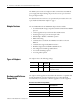
B Appendix Specifications Overview This appendix contains general and environmental specifications and certifications for the FLEX I/O Dual Port EtherNet/IP Adapter Modules. General Specifications – 1794-AENTR, 1794-AENTRXT Specification 1794-AENTR I/O capacity 8 modules Power supply To comply with the CE Low Voltage Directive (LVD), this equipment must be powered from a source compliant with the following: Safety Extra Low Voltage (SELV) or Protected Extra Low Voltage (PELV).
54 Specifications Environmental Specifications – 1794-AENTR, 1794-AENTRXT Publication 1794-UM066A-EN-P - February 2012 Specification 1794-AENTR 1794-AENTRXT Temperature, operating IEC 60068-2-1 (Test Ad, Operating Cold), IEC 60068-2-2 (Test Bd, Operating Dry Heat), IEC 60068-2-14 (Test Nb, Operating Thermal Shock): 0…55 °C (32…131 °F) -25 …70 °C (-13…158 °F) Temperature, surrounding air, max 55 °C (131 °F) 70 °C (158 °F) Temperature, nonoperating IEC 60068-2-1 (Test Ab, Unpackaged Nonoperating
Specifications Certifications Certifications (when product is marked)(1) Value c-UL-us UL Listed Industrial Control Equipment, certified for US and Canada. See UL File E322657. UL Listed for Class I, Division 2 Group A,B,C,D Hazardous Locations, certified for U.S. and Canada. See UL File E334470. CE European Union 2004/108/EC EMC Directive, compliant with: EN 61326-1; Meas./Control/Lab.
56 Specifications Notes: Publication 1794-UM066A-EN-P - February 2012
Appendix C Configure the RSLinx Ethernet Communication Driver Overview Read this appendix to install, and configure the AB_ETH driver. For Information On Page About the Etherner Communication Driver 57 Install the RSLinx Software 57 Configure the AB_ETH Driver 57 About the Etherner Communication Driver In order to communicate with your 1794-AENTR or 1794-AENTRXT adapters over your network you must configure the RSLinx Ethernet communication driver (AB_ETH).
58 Configure the RSLinx Ethernet Communication Driver 1. Start RSLinx. 2. From the Communications menu, select Configure Drivers. 3. From the Available Driver Types drop down menu, select Ethernet Devices, and then click Add/New. The Add New RSLinx Driver dialog box appears. 4. Select the default driver name (for example, AB_ETH-1) or type in your own name and click OK. The Configure driver dialog appear with the Station Mapping tab open. 5.
Configure the RSLinx Ethernet Communication Driver 59 7. When you are done entering the IP addresses, click Apply and then click OK to close the Configure driver window. The new driver appears in the list of configured drivers. Your list displays the drivers you have configured on your workstation. 8. Close RSLinx.
60 Configure the RSLinx Ethernet Communication Driver Notes: Publication 1794-UM066A-EN-P - February 2012
Appendix D Adapter Web Dialogs Overview Work with the Home Page The Web server dialog of the FLEX I/O adapter offers extensive internal and network diagnostics. To view the Web dialogs, enter the IP address of the FLEX I/O adapters into your browser.
62 Adapter Web Dialogs 1. From your web browser, enter the adapter IP address to see the Home page. Enter the adapter IP address to see the home page. 2. From the Home page, click Expand to show options, or minimize to see Diagnostics and Configuration. Click Expand to show options. 3. From the Home page, complete one of these, as desired. • Click one of the following to access www.ab.com. – Allen-Bradley logo at the top of the page – AB.
Adapter Web Dialogs Work with the Diagnostics Pages To work with the Diagnostics options, follow these procedures. 1. From the Home page, click Diagnostics or Expand to see the following diagnostics options from the panel at the left. • Diagnostic Overview • Network Settings • Ethernet Statistics • I/O Connections 2. In the Refresh Rate field, you can type a refresh rate, noting that the default rate is 15 seconds. 3.
64 Adapter Web Dialogs Use the Diagnostic Overview Page To use the Diagnostic Overview page for general diagnostics information, click Diagnostic Overview from the tab at the top of the page or panel on the left.
Adapter Web Dialogs Use the Network Settings Page To use the Network Settings page for network related information, click Network Settings tab at the top of the page or panel on the left. This opens the Network Settings page.
66 Adapter Web Dialogs Use the Ethernet Statistics Page To use the Ethernet Statistics page for information about the Ethernet link and interface and media counters, click Ethernet Statistics tab at the top of the page or from the panel on the left. The Ethernet Statistics page opens.
Adapter Web Dialogs 67 – FCS Errors – Single Collisions – SQE Test Errors – Deferred Transmissions – Late Collisions – Excessive Collisions – MAC Transmit Errors – Carrier Sense Errors – Frame Too Long – MAC Receive Errors • Interface Counters – In Octets – In Ucast Packets – In NUcast Packets – In Discards – In Errors – In Unknown Protos – Out Octets – Out UCast Packets – Out NUcast Packets – Out Discards – Out Errors Use the I/O Connections Page To use the I/O Connections page for CIP I/O (Class 1) con
68 Adapter Web Dialogs • • • • • • • • Work with the Configuration Pages Received / Transmitted packets Connection ID Source Destination Multicast Address RPI Lost Packets Size To work with the Configuration pages, follow these procedures. IMPORTANT The values on these pages are in non-volatile memory. Changes to these parameters do not take effect until you reset or cycle power through the FLEX I/O adapter.
Adapter Web Dialogs 69 A login dialog opens as shown. The dialog may vary in appearance depending on your operating system and browser. 3. From the user name and password dialog, enter values, noting the following: • The values for user name and password are case sensitive. • The default user name is “Administrator”. • The default password is "". 4. Click OK to log in. After you log in, you can go to any of the Configuration pages without having to log in again. 5.
70 Adapter Web Dialogs The Identity page opens. From the Identity page, complete entries for the following, noting that the description and location help you identify where modules are in the facility: • Host Name • Module Description • Module Location 6. Click Apply Changes to save the modified values.
Adapter Web Dialogs 71 The Network Configuration page opens. From the Network Configuration page, complete these entries, noting that values for Network Interface are disabled when DHCP is Dynamic DHCP and port speed and duplex mode are disabled when Autonegotiate Speed and Duplex is selected.
72 Adapter Web Dialogs – Secondary Name Server – Domain Name • For Ethernet Link Port 1 and Port 2, specify the following: – Autonegotiate Status - Autonegotiate Speed and Duplex - Force Speed and Duplex – Select Port Speed – 10 megabits, 100 megabits – Select Duplex Mode – Half Duplex, Full Duplex 7. From the Network Configuration page, click Apply Changes to save the modified values.
Index Numerics 1756-EN2TR 24, 38 module 28, 38 1756-EN2TR bridge 27 1756-EN2TR module 24, 28, 38 1794-IB16 24 A AB_ETH 35, 38, 48, 57, 58 configured 24 ethernet communication driver 57 adapter 1, 7 1794-AENTR iii, 2, 3, 5, 7, 15, 23, 24, 26, 27, 28, 29, 30, 33, 37, 38, 40, 42, 45, 51, 57 1794-AENTRXT iii, 2, 3, 5, 7, 15, 57 add 27 bridge 3 cabling components 2 child 27 CIP protocol 3 communicating through 5 compatibility 2 connect or disconnect 9 connection to 5 diagnostics 61 EDS file 63 Ethernet hardware
74 Index gateway 18 gateway address 15 IP address 15 new adapter 15 rack connection 23 routing tables 3 RPI 5 RSLinx 24, 38 subnet mask 15 TCP/IP settings 61 configure driver window 59 connection adjacent 9 backplane 9 direct 4, 37, 41, 44 I/O 62 power wiring 9 rack 41, 44 rack optimized 4, 23 single 5 connection point 9 connections 84 I/O 63 connector FlexBus 9 controller Logix5572 23 conventions iv corresponding IP address 20 D data 24 configuration 1, 4 consumed 4 exchange 4 I/O 3, 5 input 3 messaging
Index FLEX I/O 23 adapter 1 description 1 I/O module 1 module components 7 system 1 terminal base 1 FLEX I/O module 2, 29 FLEX I/O system 1 components 1 definition 1 FlexBus connector 9 G gateway 16 gateway address 12, 15, 16 configure 15 Internet Protocol IP 12 invalid number thumbwheel switches 12 IP Internet Protocol 12 IP Address 19, 27 IP address 2, 12, 15, 16, 17, 20, 57, 58, 61, 62 adapter 22 class 16 configure 15 corresponding 20 dotted-decimal 16 gateway 17 retrieve 12 switches 7 unique 15, 16 v
76 Index FLEX I/O 2, 29 I/O 1, 3, 4, 5, 8, 26 input 3, 23, 29, 37 input, add 30 insert or remove 9 latching mechanism 9 location 61 locking tab 7 name 61 output 23, 29, 37 output, add 31 reinstall 10 settings 64 type 26 uptime 64 module capacity 2 module description 61 module location 61 module name 61 module settings 64 module type 26 module uptime 64 modules analog input 37 analog output 37 N Net ID 16 net ID 17, 18 network 3 cable 11 devices 3 EtherNet/IP 3, 4, 7 scheduling 2 TCP/IP 21 traffic 3 netwo
Index status indicators 7, 51 subnet mask configure 15 switches IP address 7 thumbwheel 12 T TCP/IP network 21 protocol iii terminal base 1, 2, 9 adjacent 9, 10 unit 9 thumbwheel settings 12 switches 12 thumbwheel switches invalid number 12 read 12 transfer data 4 unique 48-bit hardware address 15 combination of bits 18 IP address 15, 52 unique IP address 15 W web dialogs CIP connection statistics 64 configuration 68 diagnostic overview 63, 64 ethernet statistics 63, 66 home page 61 I/O connections 63,
78 Index Notes: Publication 1794-UM066A-EN-P - February 2012
Rockwell Automation Support Rockwell Automation provides technical information on the Web to assist you in using its products. At http://www.rockwellautomation.com/support/, you can find technical manuals, a knowledge base of FAQs, technical and application notes, sample code and links to software service packs, and a MySupport feature that you can customize to make the best use of these tools.