
User Manual

FLEX I/O 5V dc TTL Digital Input and Output Modules 3
Publication 1794-IN119A-EN-P - June 2008
Ground Your Module
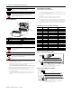
Use shielded communication cable (Belden #8761). The Belden cable has two signal
wires (black and clear), one drain wire, and a foil shield. The drain wire and foil
shield must be grounded at one end of the cable.
Configure Your Input Module
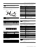
You configure your input module by setting bits in the configuration word (word 3).
Set the Input Filter Time for the 1794-IG16
To set the input filter time, set the associated bits in the output image
(complementary word) for the module.
Input Filter Times
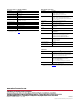
Configure Your Output Module
You configure your output module by setting bits in word 1.
IMPORTANT
To comply with the CE Low Voltage Directive (LVD), all connected I/O must
be powered from a source compliant with the following: Safety Extra Low
Voltage (SELV) or Protected Extra Low Voltage (PELV).
IMPORTANT
Do not ground the drain wire and foil shield at both ends of the cable.
Dec 15 14 13 12 11 10 9 8 7 6 5 4 3 2 1 0
Oct 17 16 15 14 13 12 11 10 7 6 5 4 3 2 1 0
Read I15 I14 I13 I12 I11 I10 I9 I8 I7 I6 I5 I4 I3 I2 I1 I0
Write Not used = Set to 0 Input filter FT1
12-15
Input filter FT0
0-11
Where I = Input
FT0 = Input filter time for inputs 0-11
FT1 = Input filter time for inputs 12-15
Bits Description Selected Filter Time
02 01 00 Filter Time for inputs 00...11
05 04 03 Filter Time for inputs 12...15
0 0 0 Filter Time 0 (Default) 0.25ms
0 0 1 Filter Time 1 0.50ms
0 1 0 Filter Time 2 1ms
0 1 1 Filter Time 3 2ms
1 0 0 Filter Time 4 4ms
1 0 1 Filter Time 5 8ms
1 1 0 Filter Time 6 16ms
1 1 1 Filter Time 7 32ms
Dec 15 14 13 12 11 10 9 8 7 6 5 4 3 2 1 0
Oct 17 16 15 14 13 12 11 10 7 6 5 4 3 2 1 0
Read Not used - Set to 0
Write O15 014 013 012 011 010 O9 O8 O7 O6 O5 O4 O3 O2 O1 O0
Where O = Output
Foil Shield
Black Wire
Drain Wire
Clear Wire
Insulation
O:010
09 08 07 06 05 04 03 02 01
00
15 14 13 12 11 10
Dec.
FT = 12 thru 15 FT = 00 thru 11
Specifications - 1794-IG16 Flex I/O 5V dc TTL Digital Input Module
Specification Description
Number of I/O channels 16, nonisolated
Module location Cat. No. 1794-TB3, -TB3S
On-state voltage -0.2V dc...0.8V dc typical
Input current 3.7mA nominal @ 5V dc
4.1mA maximum @ 5V dc
Off-state voltage 2.0...5.5V dc typical
Off-state current 4.1mA maximum
Input impedance 1.4K ohms minimum
1.5K ohms typical
Isolation voltage 50V (continuous), Basic Insulation Type, between field side and system
Type tested at 707V dc for 60 s, between field side and system
No isolation between individual channels
Flexbus current 40mA
Power dissipation 1.4W maximum @ 5.5V dc
Thermal dissipation 4.78 BTU/hr @ 5.5V dc
Indicators (field side indication,
customer device driven)
16 yellow status indicators
Input filter time
(1)
Off to On
On to Off
(1)
Input off-to-on filter time is the time from a valid input signal to recognition by the module.
Input on-to-off filter time is time from the input signal dropping below the valid level to recognition by the module.
0.25ms, 0.5ms, 1ms, 2ms, 4ms, 8ms, 16ms, 32ms
0.25ms, 0.5ms, 1ms, 2ms, 4ms, 8ms, 16ms, 32ms
IMPORTANT
TTL inputs are inverted
(-0.2…0.8V dc=logic low voltage=1=on
2.0…5.5V dc=logic high voltage=0=off).
Use a NOT instruction in the ladder program to convert to traditional
true=High logic.
Specifications - 1794-OG16 Flex I/O 5V dc TTL Digital Output Module
Specification Description
Number of I/O channels 16, nonisolated
Module location Cat. No. 1794-TB3, -TB3S
On-state voltage 0V dc...0.4V dc
Output current rating 24mA maximum per channel
Off-state voltage 4.5V...5.5V dc typical
On-state current 0.15mA minimum per channel
24mA maximum per channel
Off-state leakage 0.1mA maximum
Isolation voltage 50V (continuous), Basic Insulation Type, between field side and system
Type tested at 707V dc for 60 s, between field side and system
No isolation between individual channels
Output signal delay
(1)
(Resistive load)
(1)
The time from the receipt of an on or off command to the output actually turning on or off.
Off to On - 0.25ms maximum
On to Off - 0.5ms maximum
Flexbus current 80mA
Power dissipation 0.8W maximum @ 5.5V dc
Thermal dissipation 3.41 BTU/hr maximum @ 5.5V dc
Pilot duty rating Not rated
Indicators (field side indication,
customer device driven)
16 yellow status indicators
IMPORTANT
TTL outputs are inverted
(On=1=logic low voltage=0…0.4V dc;
Off=0=logic high voltage=4.5…5.5V dc).
Use a NOT instruction in the ladder program to convert to traditional
true=High logic.