
Installation Instructions Manual

4
Publication 1794-IN103B-EN-P - May 2011
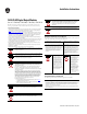
1794-TB2, 1794-TB3, 1794-TB3S Terminal Base Wiring for 1794-OA16
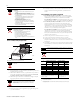
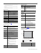
1794-TBN Terminal Base Wiring for 1794-OA16
Configure the FLEX I/O AC Output Module
Specifications
10 A-10 B-27 B-10
11 A-11 B-28 C-11
12 A-12 B-29 B-12
13 A-13 B-30 C-13
14 A-14 B-31 B-14
15 A-15 B-32 C-15
120V AC L1
power
Connect V AC L1 to C-34.
1794-TB3, 1794-TB3S – Power terminals C-34…C-51 are internally connected together.
1794-TB2 and 1794-TBN – C-34 and C-51 are internally connected together.
120V AC L2
common
Connect 120V AC common L2 to terminal B-16.
1794-TB3, 1794-TB3S – 120V AC common L2 terminals B-16…B-33 are internally connected together.
1794-TB2, 1794-TBN – 120V AC common L2 terminals B-16 and B-33 internally connected together.
(1)
Auxiliary terminal blocks are required to connect the associated L2 common for each channel when
using a 1794-TBN terminal base with the 1794-OA16.
Image Table Memory Map for the 1794-OA8, 1794-OA8K and 1794-OA8I
Dec 15 14 13 12 11 10 9 8 7 6 5 4 3 2 1 0
Oct 17 16 15 14 13 12 11 10 7 6 5 4 3 2 1 0
Read Not used – set to 0
Write Not used – set to 0 O7 O6 O5 O4 O3 O2 O1 O0
Where: O = Output number
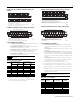
Wiring Connections for 1794-OA16
Output
Channel
1794-TB2, 1794-TB3, 1794-TB3S 1794-TBN
Output Terminal 120V AC Common (L2)
Output Terminal
(1)
17 18 19 20 21 22 23 24 25 26 27 28 29 30 31 32 33
0 1 2 3 4 5 6 7 8 9 10 11 12 13 14 15
16
35 36 37 38 39 40 41 42 43 44 45 46 47 48 49 50 51
34
Commons
(1794-TB3 shown)
Connect 120V AC common L2 to terminal B-16.
Connect 120V AC power L1 to terminal C-34.
L2 IN L2 OUT
Voltage
A
B
C
(Use B-33 and C-51 for daisy-chaining power to the next terminal base unit.)
L1 IN L1 OUT
(Terminals C-35…C-50 are not present on the 1794-TB2.)
Outputs
45675
16
0
1
2
3
4
5
6
7
8
9
10
11
12
13
14
15
51
33
34
B
C
Even Numbered I/O Terminals 0…14
Odd Numbered I/O Terminals 1…15
Connect 120V AC (L2) to terminal B-16
Connect 120V AC power (L1) to terminal C-34
Use B-33 and C-51 for daisychaining to the next terminal base
L1
L2
L1
L2
45676
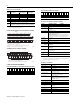
Image Table Memory Map for the 1794-OA16
Dec 15 14 13 12 11 10 09 08 7 6 5 4 3 2 1 0
Oct 17 16 15 14 13 12 11 10 7 6 5 4 3 2 1 0
Read Not used - set to 0
Write O15 O14 O13 O12 O11 O10 O9 O8 O7 O6 O5 O4 O3 O2 O1 O0
Where: O = Output number
Specifications for 1794-OA8, 1794-OA8K and 1794-OA8I
Attribute
1794-OA8, 1794-OA8K 1794-OA8I
Number of outputs 8, (1 group of 8), nonisolated 8, isolated
Module location 1794-TB2, 1794-TB3, 1794-TB3S, 1794-TBN and 1794-TBNF
Output voltage range 85V AC, min
120V AC, nom
132V AC, max
Output current rating 4.0A (8 outputs @ 500 mA)
On-state current
5.0 mA per output min
500 mA per output max @ 55 °C (sufficient to operate an Allen-Bradley
Bulletin 500 NEMA size 3 motor starter)
750 mA per output max @ 35 °C
1.0A on 4 nonadjacent outputs, 500 mA on the remaining 4 outputs @ 30 °C
NOTE
: Below 50 mA the voltage drop across the module will be higher and
the voltage waveform may have some small oscillation (less than 5V).
Voltage drop,
on-state, max
1.0V @ 0.5A
Leakage current,
off-state, max
2.25 mA
Surge current 7A for 40 ms, repeatable every 8 s
Output signal delay
(1)
Off to On
On to Off
(1)
Output signal delay is the time from receipt of an output on or off command to the output actually
turning on or off.
1/2 cycle, max
1/2 cycle, max
Power dissipation, max
4.1W @ 0.5A
6.3W @ 0.75A
6.3W @ 1.0A
Thermal dissipation 14.0 BTU/hr @ 0.5 A
21.2 BTU/hr @ 0.75 A
21.4 BTU/hr @ 1.0 A
FlexBus current 80 mA @5V DC
Fusing
(2)
(2)
Module outputs are not fused. Fusing is recommended. If fusing is desired, you must supply external
fusing or use the 1794-TBNF terminal base, if recommended.
1.6A, 250V AC slow-blow, Littelfuse 23901.6; San-O SD6-1.6 (1.6A fuses
come preinstalled in 1794-TBNF terminal base units.)
Specifications for 1794-OA16
Attribute
Value
Number of outputs 16, nonisolated
Module location
1794-TB2, 1794-TB3, 1794-TB3S and 1794-TBN3
(3)
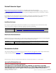
Mounting See derating curve
Output voltage range 74V AC min, 47…63 Hz
120V AC nom, 47…63 Hz
132V AC max, 47…63 Hz
Output current rating 4.0A (16 outputs @ 250 mA)
Attention: If using 0.5A outputs, alternate wiring so that no
two 0.5 A outputs are next to each other.
On-state current 5.0 mA per output, min
500 mA per output @ 55 °C, max
NOTE: Below 50 mA the voltage drop across the module will
be higher and the voltage waveform may have some small
oscillation (less than 5V).
On-state voltage drop, max 1.5V @ 0.5 A
Off-state leakage current, max 2.25 mA
Surge current 7 A for 40 ms, repeatable every 8 s
Output signal delay
(1)
Off to On
On to Off
1/2 cycle, max
1/2 cycle, max
Power dissipation, max 4.7W @ 0.5A
Thermal dissipation 16.1 BTU/hr @ 0.5 A
FlexBus current 80 mA @ 5V DC
Fusing
(2)
2.5A, 150V AC normal blow, MQ2