USER MANUAL BULLETIN 193 E1 Plus DeviceNet™ Module CATALOG NUMBER 193-EDN
Important User Information Solid state equipment has operational characteristics differing from those of electromechanical equipment. Safety Guidelines for the Application, Installation and Maintenance of Solid State Controls (Publication SGI-1.1 available from your local Rockwell Automation sales office or online at http://www.ab.com/manuals/gi) describes some important differences between solid state equipment and hard-wired electromechanical devices.
Table of Contents Chapter 1 — Installation and Wiring Introduction . . . . . . . . . . . . . . . . . . . . . . . . . . . . . . . . . . . . . . . . . . . . . Features. . . . . . . . . . . . . . . . . . . . . . . . . . . . . . . . . . . . . . . . . . . . . . . . . Installation . . . . . . . . . . . . . . . . . . . . . . . . . . . . . . . . . . . . . . . . . . . . . . Wiring . . . . . . . . . . . . . . . . . . . . . . . . . . . . . . . . . . . . . . . . . . . . . . . . . . Dimensions. . . . . . . . . . . . .
iv Appendix A — Specifications . . . . . . . . . . . . . . . . . . . . . . . . . . . . . . . . . . . . . . . . . . . . . . . . . . . . . . . A-1 Appendix B — DeviceNet Information Electronic Data Sheets. . . . . . . . . . . . . . . . . . . . . . . . . . . . . . . . . . . . . B-1 DeviceNet Objects. . . . . . . . . . . . . . . . . . . . . . . . . . . . . . . . . . . . . . . . B-1 Identity Object — CLASS CODE 0x0001 . . . . . . . . . . . . . . . . . B-2 Message Router — CLASS CODE 0x0002 . . . . . . . . .
Chapter 1 Installation and Wiring Introduction The purpose of this chapter is to provide the necessary instructions to successfully install a 193-EDN DeviceNet Module to an E1 Plus Overload Relay and properly connect to a DeviceNet network. ATTENTION ATTENTION ATTENTION ATTENTION 1 To prevent electrical shock, disconnect from power source before installing or servicing. Install in suitable enclosure. Keep free from contaminants.
1-2 Installation and Wiring ATTENTION ATTENTION ATTENTION Publication 193-UM006A-EN-P – October 2005 Only personnel familiar with the side mount module and associated machinery should plan to install, set up, and maintain the system. Failure to comply may result in personal injury and/or equipment damage. This is a Class A product. In a domestic environment, this product may cause radio interference, in which case, the user may be required to take adequate measures.
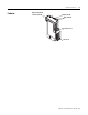
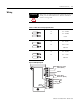
Installation and Wiring Features 1-3 Figure 1.
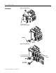
1-4 Installation and Wiring Installation Figure 1.2 Installation [1] Figure 1.3 Installation [2] #2 Driver 0.7…1.1 N•m (6…10 lb-in) Figure 1.4 Installation [3] 0.6 mm X 3.5 mm Blade (0.02 in X 0.14 in Blade) 0.5…0.6 N•m (4.4…5.3 lb.-in) Publication 193-UM006A-EN-P – October 2005 7 mm (0.
Installation and Wiring 1-5 Wiring ATTENTION When using 4-conductor DeviceNet media cable (without a shield), it is recommended that the “Shield” terminal be wired to earth ground. Table 1.1 Wire and Size Torque Specifications 1X 24…12 AWG 2X 24…16 AWG 5 lb.-in 1X 0.2…2.5 mm2 2X 0.25…1 mm2 0.55 N•m 1X 0.2…2.5 mm2 2X 0.2…1 mm2 0.55 N•m Figure 1.
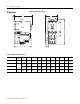
1-6 Installation and Wiring Dimensions Figure 1.6 Dimension Diagram J H A F G E K B D L C Table 1.2 Dimension Specifications Contactor Cat. No. E1 Plus Cat. No. A B C D E F G H J K L 100-C09, -C12, -C16, -C23 193*-EE_B 63 mm (2.48 in) 148 mm (4.83 in) 85.2 mm (3.35 in) 24.5 mm (0.96 in) 13.9 mm (0.55 in) 35 mm (1.38 in) 60 mm (2.36 in) 86.5 mm (3.40 in) 2 mm (0.08 in) 4.5 mm (0.17 in) 18 mm (0.71 in) 100-C30, -C37 193*EE_D 63 mm (2.48 in) 148 mm (5.83 in) 101.2 mm (3.
Chapter 2 Protection Functions Introduction The purpose of this chapter is to provide detailed information regarding the protective trip and warning functions that the 193-EDN DeviceNet Module adds to the E1 Plus Overload Relay. In this chapter, you will find considerable mention given to parameters as they relate to these functions. For complete descriptions of the programming parameters, refer to Chapter 4 - Device Parameters.
2-2 Protection Functions Parameter 13, Warning Enable, allows the installer to enable or disable the overload, jam and underload warning protective functions. ATTENTION Overload and Phase Loss Protection The Trip Enable settings should not be altered during machine operation, as unexpected behavior could occur. This may result in an unintended actuation of controlled industrial equipment, with the potential for machine damage or serious injury to personnel.
Protection Functions IMPORTANT Jam Protection 2-3 %Therm Utilized will stabilize at a value of approximately 88% with the motor operating continuously at rated current. Motor current greater than the motor's nameplate rating can indicate a high overload or stall condition, such as an overloaded conveyor or jammed gear. These conditions can result in overheating of the motor, and equipment damage. Rapid jam fault detection helps to minimize damage and loss of production.
2-4 Protection Functions • The E1 Plus Overload Relay's trip relay contacts (95 and 96) will open • Out A will be placed in their Protection Fault State (if so programmed) IMPORTANT IMPORTANT The Protection Fault State of OUT A is defined by parameter 34 (OUTA Pr FltState) and parameter 35 (OUTA Pr FltValue). The jam inhibit timer starts after the load current transitions from 0 A to 30% FLA. The DeviceNet Module does not begin monitoring for a jam condition until the Jam Inhibit Time expires.
Protection Functions 2-5 Underload Warning The following parameters are available for configuring the DeviceNet Module's underload warning performance: • Parameter 22, UL Inhibit Time, allows the installer to inhibit an underload indication from occurring during the motor starting sequence. It is adjustable from 0…250 seconds. • Parameter 23, UL Warn Level, allows the installer to define the current at which the DeviceNet Module will indicate a warning.
2-6 Protection Functions When the Comm Fault warning conditions are satisfied, the following will occur: • The Network Status LED will blink red or become solid red • Bit 5 in Parameter 4, Warning Status, will go to “1” • Bit 1 of Parameter 10, Device Status, will go to “1” IMPORTANT Communication Idle Protection The Comm Fault State of OUT A is defined by Parameter 36 (OUTA Dn FltState) and parameter 37 (OUTA Dn FltValue).
Chapter 3 DeviceNet Node Commissioning Using RSNetWorx for DeviceNet Going Online To begin the configuration of an E1 Plus DeviceNet Module, execute the RSNetWorx software and complete the following procedure. You must use RSNetWorx Revision 3.21 Service Pack 2 or later. 1. After going on-line using RSNetWorx for DeviceNet, do the following: • Select the Network menu. • Select Online. 2. Choose the appropriate DeviceNet PC interface. In this example, a 1784-PCD module is chosen.
3-2 DeviceNet Node Commissioning Figure 3.1 Network Online Screen 6. If RSNetWorx recognizes the device as an E1 Plus Overload Relay, skip ahead to the following section - Using the Node Commissioning Tool of RSNetWorx for DeviceNet. Building and Registering an EDS File The EDS file defines how RSNetWorx for DeviceNet will communicate to the E1 Plus DeviceNet Module. The EDS file can be created over the DeviceNet network or downloaded from the Internet. Note: You can download the EDS file from www.ab.
DeviceNet Node Commissioning 3-3 Figure 3.2 Figure EDS Wizard Screen 6. (Optional) Do the following: • Type a value in Catalog. • Type a description in File Description Text. 7. Select Next. Figure 3.
3-4 DeviceNet Node Commissioning 8. Next to the selected Polled check box, do the following: • Type 6 in Input Size. • Type 1 in Output Size. 9. Select Next. RSNetWorx uploads the EDS file from the E1 Plus DeviceNet Module. 10. To display the icon options for the node, select Next. 11. Select the E1 Plus Overload Relay icon by highlighting it and clicking Change Icon. 12. After selecting the desired icon, select OK. 13. Select Next. 14. When prompted to register this device, select Next. 15.
DeviceNet Node Commissioning 3-5 3. Select the E1 Plus Overload Relay located at node 63. 4. Select OK. The Node Commissioning screen shows Current Device Settings entries completed. It will also provide the current network baud rate in the New E1 Plus Overload Relay Settings area. Do not change the baud rate setting, unless you are sure it must be changed. 5. Type the node address that you want in the New Device Settings section. In this example, the new node address is 5. 6.
3-6 DeviceNet Node Commissioning Produced and Consumed Assembly Configuration The Input and Output Assembly format for the E1 Plus Overload Relay is identified by the value in Parameter 28 (Output Assembly) and Parameter 29 (Input Assembly). These values determine the amount and arrangement of the information communicated to the master scanner. Figure 3.
DeviceNet Node Commissioning 3-7 Table 3.2 Instance 110—E1 Plus Default Input (Produced) Assembly Instance 110 – Extended Motor Starter Input Assembly Byte Bit 7 0 Motor Current Bit 6 Bit 5 Bit 4 Input2 Input1 1 Bit 3 Bit 2 Bit 1 Bit 0 OutA Stat Warning Faulted Unused 2 Average %FLA 3 4 %Therm Utilized 5 Choosing the size and format of the I/O data that is exchanged by the E1 Plus Overload Relay is done by selecting Input and Output Assembly instance numbers.
3-8 DeviceNet Node Commissioning Figure 3.7 Editing Device I/O Parameters Commissioning the Protection Functions The product should now be configured and communicating on the network. This section describes the use of RSNetWorx for DeviceNet to configure the additional protective function settings of the E1 Plus DeviceNet Module. This can also be accomplished by using a handheld DeviceNet tool. Using the software, access the Device Parameters tab (see Figure 3.8).
Chapter 4 Device Parameters Introduction This chapter describes each programmable parameter and its function. Parameter Programming Refer to Chapter 3: DeviceNet Node Commissioning for instructions on using RSNetWorx for DeviceNet to modify parameter settings. IMPORTANT IMPORTANT Parameter setting changes downloaded to the DeviceNet Module take effect immediately even during a “running” status.
4-2 Device Parameters Parameter Group Listing The 193-EDN DeviceNet Module contains six parameter groups Table 4.
Device Parameters Trip Status Parameter No. 3 This parameter provides trip identification. Access Rule Get Data Type WORD Group Monitor Units — Min. Value — Max. Value — Default Value None 1 = Trip 0 = No Trip Bit 15 14 13 12 11 10 9 8 7 Function: 6 5 4 3 2 1 0 X X X X X X X X X X X X X Jam X Not Used Warning Status Parameter No. 4 This parameter provides warning identification Access Rule Get Data Type WORD Group Monitor Units — Min.
4-4 Device Parameters Device Status Parameter No. 10 This parameter provides status information related to the E1 Plus Overload Relay and the DeviceNet Module. Access Rule Get Data Type WORD Group Monitor Units — Min. Value — Max.
Device Parameters Bit 15 14 13 12 11 10 9 8 7 Function: 6 5 4 3 2 1 0 X Trip X Warning X Out A X In 1 X In 2 X X X X X X X X X X 4-5 Motor Current X Not Used Firmware Parameter No. 11 This parameter reports the firmware revision of the DeviceNet Module. Access Rule Get Data Type UINT Group Monitor Units — Min. Value 0 Max. Value 65535 Default Value None Advanced Setup Group Trip Enable Parameter No.
4-6 Device Parameters Bit 15 14 13 12 11 10 9 8 7 Function: 6 5 4 3 2 1 0 X X Not Used X X X X X X X X X X X X X Not Used Jam X Not Used Warning Enable Parameter No. 13 This parameter allows the installer to enable or Access Rule disable the warning functions separately. All Data Type warning functions are disabled from the factory. Group 1 = Enabled Units 0 = Disabled Min.
Device Parameters OL Reset Mode Parameter No. 16 This parameter defines whether a trip can be automatically or manually reset. This setting overrides the E1 Plus DIP switch adjustment while the DeviceNet Module is powered. Note, however, that the E1 Plus manual reset button, accessible at the front, is always active. Access Rule Get/Set Data Type BOOL Group Advanced Setup Units — Min. Value 0 = Manual Max. Value 1 = Automatic Default Value 0 OL Warning Level Parameter No.
4-8 Device Parameters Publication 193-UM006A-EN-P – October 2005 Jam Trip Level Parameter No. 20 This parameter sets the jam trip level. Access Rule Get/Set Data Type UINT Group Advanced Setup Units % FLA Min. Value 150 Max. Value 600 Default Value 250 Jam Warn Level Parameter No. 21 This parameter sets the jam warning level. Access Rule Get/Set Data Type UINT Group Advanced Setup Units % FLA Min. Value 100 Max. Value 600 Default Value 150 UL Inhibit Time Parameter No.
Device Parameters 4-9 Reset/Lock Group Trip Reset Parameter No. 14 This parameter provides the user with the capability of resetting a trip over the DeviceNet network. After a trip is reset, the parameter automatically returns to a “Ready” state. Access Rule Get/Set Data Type BOOL Group Reset/Lock Units — Min. Value 0 = Ready Max. Value 1 = Reset Trip Default Value 0 Program Lock Parameter No.
4-10 Device Parameters DeviceNet Setup Group AutoBaudEnable Parameter No. 26 When this parameter is enabled, the device will attempt to determine the network baud rate and set its baud rate to the same, provided network traffic exists. At least one node with an established baud rate must exist on the network for autobaud to occur. Access Rule Get/Set Data Type BOOL Group DeviceNet Setup Units — Min. Value 0 = Disabled Max. Value 1 = Enabled Default Value 1 NonVol Baud Rate Parameter No.
Device Parameters Assy Word 0 Param Parameter No. 30 This parameter assigns the parameter value to be placed in Word 0 of Input Assembly 100. Access Rule Get/Set Data Type USINT Group DeviceNet Setup Units — Min. Value 0 Max. Value 41 Default Value 1 Assy Word 1 Param Parameter No. 31 This parameter assigns the parameter value to be placed in Word 1 of Input Assembly 100. Access Rule Get/Set Data Type USINT Group DeviceNet Setup Units — Min. Value 0 Max.
4-12 Device Parameters I/O Setup Group OutA Pr FltState Parameter No. 34 This parameter, in conjunction with parameter 35, defines how Output A will respond when a trip occurs. When set to “1”, Output A will continue to operate as commanded via the network. When set to “0”, Output A will open or close as determined by the setting of parameter 35. Access Rule Get/Set Data Type BOOL Group I/O Setup Units — Min. Value 0 = Go To FltValue (#35) Max.
Device Parameters 4-13 OutA DN IdlState Parameter No. 38 This parameter, in conjunction with parameter 39, defines how Output A will respond when the DeviceNet network is idle. When set to “1”, Output A will hold the state prior to trip occurrence. When set to “0”, Output A will open or close as determined by the setting in Parameter 39. The DN Flt parameters supersede the DN Idl parameters. Access Rule Get/Set Data Type BOOL Group I/O Setup Units — Min. Value 0 = Go To IdlValue (#39) Max.
4-14 Device Parameters Trip History Group Publication 193-UM006A-EN-P – October 2005 Trip Log 0 Parameter No. 5 This parameter records the latest trip. Access Rule Get Data Type WORD Group Trip History Units — Min. Value See Trip Status table Max. Value See Trip Status table Default Value None Trip Log 1 Parameter No. 6 This parameter records the trip previous to Trip Log 0. Access Rule Get Data Type WORD Group Trip History Units — Min. Value See Trip Status table Max.
Device Parameters 4-15 Trip Log 4 Parameter No. 9 This parameter records the trip previous to Trip Log 3. Access Rule Get Data Type WORD Group Trip History Units — Min. Value See Trip Status table Max.
4-16 Device Parameters Publication 193-UM006A-EN-P – October 2005
Chapter 5 Troubleshooting Introduction The purpose of this chapter is to assist in troubleshooting the E1 Plus DeviceNet module. ATTENTION ATTENTION 1 Servicing energized industrial control equipment can be hazardous. Electrical shock, burns, or unintentional actuation of controlled industrial equipment may cause death or serious injury.
5-2 Troubleshooting DeviceNet Modes of Operation The E1 Plus DeviceNet Module has four DeviceNet modes of operation: Power-up Reset Mode, Run Mode, Recoverable Error Mode, and Unrecoverable Error Mode. Power-Up Reset Mode During power-Up Reset Mode, the following occurs: 1. The NETWORK STATUS LED should flash green for approximately 1/4 second, then red for 1/4 second. If autobaud is enabled and the E1 Plus DeviceNet Module is not connected to an active network, this LED will not continue to flash.
Troubleshooting 5-3 Recoverable Error Mode In Recoverable Error Mode, the E1 Plus DeviceNet Module’s NETWORK STATUS LED turns solid red. The overload relays will respond to messages that are specified in offline node recovery message protocol. Error Type Description LED State Recoverable Duplicate node address detected Solid Red Unrecoverable Error Mode In Unrecoverable Error Mode, the E1 Plus DeviceNet Module’s NETWORK STATUS LED turns solid red.
5-4 Troubleshooting DeviceNet Troubleshooting Procedures The following table identifies possible causes and corrective actions when troubleshooting DeviceNet-related failures using the NETWORK STATUS LED. Table 5.1 DeviceNet Troubleshooting Procedures Color State None Possible Cause 1. The E1 Plus DeviceNet Module is not receiving power at the DeviceNet connector. Corrective Action Check DeviceNet power and cable connections and the power connection on the DeviceNet connector. 2.
Troubleshooting Input and Output Troubleshooting Procedures ATTENTION 5-5 If the outputs are to be commanded via an explicit message, ensure that there can never be an established I/O connection that can actively control them, and that the explicit message connection has a non-zero expected packet rate (EPR) setting. Table 5.2 Input and Output Troubleshooting Procedures Failure Type Input 1, 2 Failure Description Input 1 or 2 does not appear to recognize a contact closure Corrective Action 1.
5-6 Troubleshooting Table 5.2 Input and Output Troubleshooting Procedures (Continued) Failure Type OUT A Failure Description Output A does not appear to turn on (close) when commanded to do so. Corrective Action 1. Check the supply voltage on the DeviceNet connector. 2. Check the OUTA status LED. If the appropriate LED does not illuminate, check the programmable controller ladder logic and I/O mapping. 3.
Troubleshooting Trip and Warning Troubleshooting Procedures 5-7 The following table lists the possible causes for each trip type and the recommended action to take. Table 5.3 Trip/Warn LED Troubleshooting Procedures Overload Phase Loss Jam 1. Motor overloaded 1. Check and correct source of overload (load, mechanical transmission components, motor bearings). 2. Improper setting 2. Set FLA dial and trip class to match the motor and application requirements. 1. Missing supply phase 1.
5-8 Troubleshooting Publication 193-UM006A-EN-P – October 2005
Appendix A Specifications Terminal Ratings: Terminal Screw M3 Wire Cross Section See wiring diagram section Torque 0.5…0.6 N•m (4.4…5.3 lb.-in) Degree of Protection IP20 Power Supply Ratings: Terminals DeviceNet Connector: V+(Red), V-(Black) Rated Supply Voltage Us 24V DC Rated Operating Range Ue 11…25V DC Rated Supply Current Ie 0.23 A at 11V DC 0.10 A at 25V DC Maximum Surge Current at Power-Up 2.5 A Maximum Power Consumption 2.
A-2 Specifications Recommended Control Circuit Fuse KTK-R-6 (6 A, 600V) Rated Number of Operations Out A: W/100-C-09…100-C43 W/100-C-60…100-C85 W/NEMA Size 0…2 W/NEMA Size 3 5,000,000 2,500,000 1,000,000 300,000 Input Ratings: Terminals IN 1: IN 2: SSV (Sensor Supply Voltage) 1 2 3 Supply Voltage (provided by module) 24V DC±15% Type of Inputs Current Sinking ON-State Voltage 15V DC On-State Current (turn-on) 2 mA Steady State Current 5 mA Off-State Voltage 5V DC Off-State Current 0.
Specifications A-3 RF Immunity Test Level 10V/m Performance Criteria 1①✍ Electrical Fast Transient/Burst Immunity Test Level 2 kV (Power) 1 kV (control) Performance Criteria 1①✍ Surge Immunity Test Level 2 kV L-E 1 kV L-L Performance Criteria 1①✍ Radiated Emissions Class A Conducted Emissions Not tested ① Performance Criteria 1 requires the DUT (device under test) not to experience degradation or loss of performance. ✍ Environment 2 - Heavy Industrial. WARNING This is a class A product.
A-4 Specifications Publication 193-UM006A-EN-P – October 2005
Appendix B DeviceNet Information Electronic Data Sheets Electronic Data Sheet (EDS) files are specially formatted ASCII files that provide all of the information necessary for a configuration tool (e.g., RSNetWorx for DeviceNet) to access and alter the parameters of a device. The EDS file contains all the parameter information of a device: number of parameters, groupings, parameter name, min, max, and default values, units, data format and scaling.
B-2 DeviceNet Information Identity Object — CLASS CODE 0x0001 The following class attributes are supported for the Identity Object: Table B.2 Identity Object Class Attributes Attribute ID Access Rule Name Data Type Value 1 Get Revision UINT 1 Two instances (instance 1-2) of the Identity Object are supported. The following table shows what each instance will represent, and what the revision attribute reports: Table B.3 Identity Object Instances Inst.
DeviceNet Information B-3 The following common services are implemented for the Identity Object: Table B.5 Identity Object Common Services Implemented for: Service Code Service Name Class Instance 0x0E No Yes Get_Attribute_Single 0x10 No Yes Set_Attribute_Single 0x05 No Yes Reset Message Router — CLASS CODE 0x0002 No class or instance attributes are supported. The message router object exists only to rout explicit messages to other objects.
B-4 DeviceNet Information The following services are implemented for the DeviceNet Object: Table B.8 DeviceNet Object Common Services Implemented for: Service Code Class Instance 0x0E Yes Yes Get_Attribute_Single 0x10 No Yes Set_Attribute_Single 0x4B No Yes Allocate_Master/Slave_Connection_Set 0x4C No Yes Release_Master/Slave_Conncetion _Set Service Name Assembly Object — CLASS CODE 0x0004 The following class attributes are supported for the Assembly Object: Table B.
DeviceNet Information B-5 Input Assemblies Table B.13 Instance 50 — Basic Overload Input Assembly from ODVA Overload Profile Byte Bit 7 Bit 6 Bit 5 Bit 4 Bit 3 Bit 2 Bit 1 0 Bit 0 Tripped Table B.14 Instance 51 —Extended Overload Input Assembly from ODVA Overload Profile Byte Bit 7 Bit 6 Bit 5 Bit 4 Bit 3 Bit 2 0 Bit 1 Bit 0 Warning Tripped Table B.
B-6 DeviceNet Information The following services are implemented for the Assembly Object: Table B.
DeviceNet Information B-7 Connection Object — CLASS CODE 0x0005 No class attributes are supported for the Connection Object. Multiple instances of the Connection Object are supported, instances 2 and 4 from the group 2 predefined master/slave connection set, and instances 5-7 are available explicit UCMM connections. Instance 2 is the Polled I/O Message Connection. The following instance 2 attributes are supported: Table B.
B-8 DeviceNet Information Instance 4 is the Predefined Group 2 Connection Set Change of State/Cyclic I/O Message Connection. The following instance 4 attributes are supported: Table B.
DeviceNet Information B-9 Instances 5…7 are available group 3 Explicit Message Connections that are allocated through the UCMM. The following attributes are supported: Table B.
B-10 DeviceNet Information Discrete Input Point Object — CLASS CODE 0x0008 The following class attributes are supported for the Discrete Input Point Object: Table B.23 Discrete Input Point Object Class Attributes Attribute ID Access Rule Name Data Type Value 1 Get Revision UINT 2 2 Get Max Instance UINT 2 Two instances of the Discrete Input Point Object are supported as follows: Table B.
DeviceNet Information B-11 A single instance is implemented and contains the following attributes: Table B.
B-12 DeviceNet Information Parameter Object —CLASS CODE 0x000F The following class attributes are supported for the Parameter Object: Table B.
DeviceNet Information B-13 The following commons services are implemented for the Parameter Object: Table B.31 Parameter Object Common Services Implemented for: Service Code Class Instance 0x0E Yes Yes Get_Attribute_Single 0x10 No Yes Set_Attribute_Single Service Name Parameter Group Object — CLASS CODE 0x0010 The following class attributes are supported for the Parameter Object: Table B.
B-14 DeviceNet Information The following common services are implemented for the Parameter Group Object: Table B.34 Parameter Group Object Common Services Implemented for: Service Code Class Instance 0x0E Yes Yes Service Name Get_Attribute_Single Control Supervisor Object — CLASS CODE 0x0029 No class attributes are supported for the Control Supervisor Object. A single instance (instance 1) of the Control Supervisor Object is supported. The following instance attributes are supported. Table B.
DeviceNet Information B-15 Table B.35 Control Supervisor Object Instance Attributes Attribute ID Access Rule Name Data Type Value 104 Get Trip Log 2 WORD Last trip condition. Bit definitions of the value are the same as attribute 114. 105 GEt Trip Log 3 WORD Last trip condition. Bit definitions of the value are the same as attribute 114. 106 Get Trip Log 4 WORD Last trip condition. Bit definitions of the value are the same as attribute 114.
B-16 DeviceNet Information Acknowledge Handler Object — CLASS CODE 0x002B No class attributes are supported for the Acknowledge Handler Object. A single instance (instance 1) of the Acknowledge Handler Object is supported. The following instance attributes are supported: Table B.
DeviceNet Information B-17 6.12. Overload Object —CLASS CODE 0x002C No class attributes are supported for the Overload Object. A single instance (instance 1) of the Overload Object is supported: Table B.
B-18 DeviceNet Information A single instance (instance 1) of the DeviceNet Interface Object is supported: Table B.
DeviceNet Information B-19 ODVA Fault Codes The following ODVA fault codes are returned by the Control Supervisor Object instance attribute 13 “TripCode”. Table B.
B-20 DeviceNet Information Publication 193-UM006A-EN-P – October 2005
DeviceNet Information B-21 Publication 193-UM006A-EN-P – October 2005
B-22 DeviceNet Information Publication 193-UM006A-EN-P – October 2005
Rockwell Automation Support Rockwell Automation provides technical information on the web to assist you in using its products. At http://support.rockwellautomation.com, you can find technical manuals, a knowledge base of FAQs, technical and application notes, sample code and links to software service packs, and a MySupport feature that you can customize to make the best use of these tools.