User Manual Bulletin 193 E1 Plus EtherNet/IP Side Mount Module Catalog Number 193-ETN
Important User Information Solid-state equipment has operational characteristics differing from those of electromechanical equipment. Safety Guidelines for the Application, Installation and Maintenance of Solid State Controls (publication SGI-1.1 available from your local Rockwell Automation sales office or online at http://www.rockwellautomation.com/literature/) describes some important differences between solid-state equipment and hard-wired electromechanical devices.
Table of Contents Installation and Wiring Introduction . . . . . . . . . . . . . . . . . . . . . . . . . . . . . . . . . . . . . . . . . . . . . . . . . . . . . . 7 Features . . . . . . . . . . . . . . . . . . . . . . . . . . . . . . . . . . . . . . . . . . . . . . . . . . . . . . . . . . 8 Installation . . . . . . . . . . . . . . . . . . . . . . . . . . . . . . . . . . . . . . . . . . . . . . . . . . . . . . . 9 Wiring . . . . . . . . . . . . . . . . . . . . . . . . . . . . . . . . . . . . . . . . . . . .
Accessing Generic Module Data . . . . . . . . . . . . . . . . . . . . . . . . . . . . . . . Logix Explicit Messaging . . . . . . . . . . . . . . . . . . . . . . . . . . . . . . . . . . . . . . . . . . MicroLogix 1100 and 1400 Explicit Messaging . . . . . . . . . . . . . . . . . . . . . FactoryTalk View with Predefined Tags . . . . . . . . . . . . . . . . . . . . . . . . . . . . 44 45 48 51 Email Notifications Introduction . . . . . . . . . . . . . . . . . . . . . . . . . . . . . . . . . . . . . . . . . .
Control Supervisor Object — CLASS CODE 0x29 . . . . . . . . . . . . . Overload Object — CLASS CODE 0x2C . . . . . . . . . . . . . . . . . . . . . . PCP Object — CLASS CODE 0xC2 . . . . . . . . . . . . . . . . . . . . . . . . . . TCP/IP Interface Object — CLASS CODE 0xF5 . . . . . . . . . . . . . . Ethernet Link Object — CLASS CODE 0xF6 . . . . . . . . . . . . . . . . . . Rockwell Automation Support . . . . . . . . . . . . . . . . . . . . . . . . . . . . . . . . . . . . Installation Assistance . . . . . . .
Rockwell Automation Publication 193-UM012B-EN-P - June 2011
Chapter 1 Installation and Wiring Introduction The purpose of this chapter is to provide the necessary instructions to successfully install an E1 Plus EtherNet/IP Module to an E1 Plus Overload Relay and properly connect to a EtherNet/IP network. ATTENTION: To prevent electrical shock, disconnect from power source before installing or servicing. Install in suitable enclosure. Keep free from contaminants.
Chapter 1 ATTENTION: To remain compliant with UL/CSA Certifications, the EtherNet/IP power supply must meet NEC Class 2 requirements.
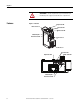
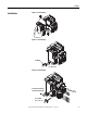
Chapter 1 Installation Figure 2 - Installation [1] Figure 3 - Installation [2] #2 Driver 0.7…1.1 N•m (6…10 lb.-in) Figure 4 - Installation [3] 0.6 mm X 3.5 mm Blade (0.02 in X 0.14 in Blade) 7 mm (0.28 in) 0.5…0.6 N•m (4.4…5.3 lb.
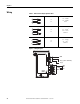
Chapter 1 Wiring Table 1 - Wire and Size Torque Specifications 1X 2X 24…12 AWG 24…16 AWG 5 lb.-in 1X 2X 0.2…2.5 mm2 0.25…1 mm2 0.56 N•m 1X 2X 0.2…2.5 mm2 0.2…1 mm2 0.56 N•m Figure 5 - Wiring Diagram GND A2 (-) 10 3 SSV IN2 13 14 1 OUTA (B300) (20.4…26.
Chapter 1 Dimensions J Figure 6 - Dimension Diagram H A F G E K B D L C Table 2 - Dimension Specifications Contactor Cat. E1 Plus A B No. Cat. No. 100-C09, -C12, 193*-EE_B 67,3 mm 148 mm -C16, -C23 (2.65 in) (4.83 in) 67,3 mm 148 mm 100-C30, -C37 (2.65 in) (5.83 in) 193*EE_D 71.8 mm 148 mm 100-C43 (2.83 in) (5.83 in) 100-C60, -C72, 193*-EE_E 94,3 mm 191.6 mm -C85 (3.71 in) (7.54 in) Network Design C 85.2 mm (3.35 in) 101.2 mm (3.98 in) 101.2 mm (3.98 in) 120.4 mm (4.74 in) D 24.5 mm (0.
Chapter 1 Rockwell Automation offers a line of Allen-Bradley managed and unmanaged Ethernet Switches with its Stratix family of Ethernet Switches (http:// www.ab.com/networks/switches/).
Chapter 2 Protection Functions Introduction The purpose of this chapter is to provide detailed information regarding the protective trip and warning functions that the E1 Plus EtherNet/IP Module adds to the E1 Plus Overload Relay. In this chapter, you will find considerable mention given to parameters as they relate to these functions. For complete descriptions of the programming parameters, refer to Chapter 6- Device Parameters and Tags.
Chapter 2 Parameter 13, Warning Enable, allows the installer to enable or disable the overload, jam, underload, and communication warning protective functions. ATTENTION: The Trip Enable settings should not be altered during machine operation, as unexpected behavior could occur. This may result in an unintended actuation of controlled industrial equipment, with the potential for machine damage or serious injury to personnel.
Chapter 2 Jam Protection Motor current greater than the motor's nameplate rating can indicate a high overload or stall condition, such as an overloaded conveyor or jammed gear. These conditions can result in overheating of the motor, and equipment damage. Rapid jam fault detection helps to minimize damage and loss of production.
Chapter 2 Jam Warning Parameter 21, Jam Warn Level, allows the installer to define the current at which the EtherNet Module will indicate a warning. It is user-adjustable from 100…600% FLA.
Chapter 2 When the Underload Warning conditions are satisfied, the following will occur: • Bit 3 in Parameter 4, Warning Status, will go to “1” • Bit 1 of Parameter 10, Device Status, will go to “1” IMPORTANT Communication Fault Protection The Underload Warning function does not include a time delay feature. Once the UL Inhibit Time has expired, the Underload warning indication is instantaneous.
Chapter 2 • No warning currently exists • Comm Idle Warning is enabled • The network controller that is communicating to the E1 Plus EtherNet/IP Module is placed in idle mode When the Comm Idle warning conditions are satisfied, the following will occur: • Bit 6 in Parameter 4, Warning Status, will go to “1” • Bit 1 in Parameter 10, Device Status, will go to “1” IMPORTANT 18 The Comm Idle State of OUT A is defined by Parameter 38 (OUTA En IdlState) and parameter 39 (OUTA En IdlValue).
Chapter 3 Configure an E1 Plus EtherNet/IP Module To Operate on the Network Introduction This chapter describes how to configure an E1 Plus EtherNet/IP module to operate on an EtherNet/IP network. When you first install an E1 Plus EtherNet/IP module, the module is Dynamic Host Configuration Protocol (DHCP) enabled. Determining Network Parameters To operate an EtherNet/IP network, you must define these parameters.
Chapter 3 Check with your Ethernet network administrator to determine if you need to specify these parameters. Setting the IP Network Address E1 Plus EtherNet/IP modules ship with DHCP enabled.
Chapter 3 5. Double-click the MAC address of the module to be configured. The MAC address is printed on the side of the E1 Plus EtherNet/IP module. The format of the hardware address resembles 00-0b-db-14-55-35. The New Entry window appears with the module’s Ethernet Address (MAC). 6. Enter the IP address, host name, and a module description. 7. Click OK. 8. Re-cycle power to the module. To recycle power, remove and reapply the control power terminals A1 and A2. 9.
Chapter 3 Assign Network Parameters Via a Web Browser and MAC Scanner Software In the event that a user does not have access to a DHCP software utility, a user can assign network parameters via a web browser, such as Microsoft’s Internet Explorer, and Media Access Control (MAC) scanner software, such as MAC Scanner from Colasoft - http://www.colasoft.com/. Follow these steps to configure the module using this method. 1.
Chapter 3 7. Open a web browser and type the IP address on the address line to view the internal web server of the E1 Plus EtherNet/IP Side Mount Module. 8. Select Administration Settings->Network Configuration to change the IP address of the E1 Plus EtherNet/IP Side Mount Module to a static IP address. 9. The module will prompt the user for a User Name and Password. Use “Administrator” for the user name, leave the password field blank, and select OK.
Chapter 3 10. Assign the appropriate network settings per the recommendation of the network administrator for the network that this module will be communicating on and select Apply. 11. Recycle the power on the E1 Plus EtherNet/IP module for the communications changes to take affect. To recycle power, remove and reapply the control power terminals A1 and A2.
Chapter 3 module. You might have to disconnect from the uplink to set the address and configure the module to retain its static address before reconnecting to the uplink. This is not a problem if you have node names configured in the module and leave DHCP enabled. ATTENTION: The E1 Plus EtherNet/IP module must be assigned a fixed network address. The IP address of this module must not be dynamically provided.
Chapter 3 DNS Addressing To further qualify a module’s address, use DNS addressing to specify a host name for a module, which also includes specifying a domain name and DNS servers. DNS addressing makes it possible to set up similar network structures and IP address sequences under different domains. DNS addressing is only necessary if you refer to the module by host name, such as in path descriptions in MSG instructions. To use DNS addressing, perform this procedure. 1. Assign a host name to the module.
Chapter 3 1. Type the IP address of the E1 Plus EtherNet/IP Side Mount Module on the address line of the web browser. 2. Right click on the EDS File link 3. Select Save to save the EDS file to the personal computer. Download EDS File from Allen-Bradley EDS File Download Site The EDS file for the E1 Plus EtherNet/IP Side Mount Module can also be downloaded from the Allen-Bradley EDS File download site.
Chapter 3 2. Select the network type as EtherNet/IP and select Search. 3. Locate the EDS file for the E1 Plus EtherNet/IP Side Mount Module and download it to the personal computer. Register the EDS File After the EDS file has been downloaded, a user will need to register the EDS file with the software that configures the EtherNet/IP network. The following example lists the steps needed to register an EDS file with Rockwell Software’s RSLinx Classic software. 1.
Chapter 3 3. Register a single file, browse to the location where the EDS file is located, and select Next. 4. Select Next to accept the installation test results.
Chapter 3 5. Accept the Graphic Image by selecting Next. 6. Select Next to register the device.
Chapter 3 7. Select Finish to successfully register the module.
Chapter 3 32 Rockwell Automation Publication 193-UM012B-EN-P - June 2011
Chapter 4 Automation Controller and Software Communications Introduction The E1 Plus EtherNet/IP Side Mount Module supports three types of EtherNet/ IP messaging: • I/O Messaging — Used for deterministic Ethernet communications with ControlLogix™, CompactLogix™, SoftLogix™, and EtherNet/IP scanners. Its primary use is to read and write I/O data for control purposes. • Explicit Messaging — Used for non-deterministic communications in which the data is not critical for control.
Chapter 4 1. Select the controller type, chassis type, slot number, and project path. Enter a name for the controller and click OK. 2. Right-click on I/O Configuration and select New Module to open the Select Module Type window.
Chapter 4 3. Select the desired EtherNet/IP scanner module and click OK. 4. Enter the desired communication settings and click Finish. EtherNet/IP Network Configuration with Add-On Profiles After the controller configuration, the E1 Plus EtherNet/IP Side Mount Module has to be added to the I/O configuration. 1. Place the program in Offline mode.
Chapter 4 2. Right-click on the Ethernet/IP scanner in I/O Configuration and select New Module to open the Select Module Type window. 3. Select E1 Plus Ethernet Module and click OK. 4. Enter a name for the E1 Plus EtherNet/IP Side Mount Module. The name will create a tag in RSLogix 5000 that can be used to read and write data from the E1 Plus EtherNet/IP Side Mount Module.
Chapter 4 5. Enter the IP address of the E1 Plus EtherNet/IP Side Mount Module. 6. Click Next. 7. The E1 Plus EtherNet/IP Side Mount Module is now shown as a module in the I/O configuration. Accessing Module Data with Add-On Profiles With both the controller and EtherNet/IP network configured, the ControlLogix controller can exchange data with the E1 Plus EtherNet/IP Side Mount Module.
Chapter 4 1. Open the Controller Tags window. 2. Select the Monitor Tags tab. Three tags, "E1Plus:C", "E1Plus:I" and "E1Plus:O", have been added to represent the three I/O Instances: Configuration, input and output. The Configuration Instance was created even though its size was configured as zero. The E1Plus:I tag represents input data, which is data coming from the E1Plus into the controller (%FLA, %TCU, Trip Status, Warning Status, etc.).
Chapter 4 1. Select the controller type, chassis type, slot number, and project path. Enter a name for the controller and click OK. 2. Right-click on I/O Configuration and select New Module to open the Select Module Type window.
Chapter 4 3. Select the desired EtherNet/IP scanner module and click OK. 4. Enter the desired communication settings and click Finish. EtherNet/IP Network Generic Configuration After the controller configuration, the E1 Plus EtherNet/IP Side Mount Module has to be added to the I/O configuration. 1. Place the program in Offline mode.
Chapter 4 2. Right-click on the Ethernet/IP scanner in I/O Configuration and select New Module to open the Select Module Type window. 3. Select Generic Ethernet Module and click OK. 4. Enter a name for the E1 Plus EtherNet/IP Side Mount Module. The name will create a tag in RSLogix 5000 that can be used to read and write data from the E1 Plus EtherNet/IP Side Mount Module. 5. Select Data-SINT for the Comm Format. The Comm Format tells RSLogix 5000 the format of the data.
Chapter 4 6. Set the Connection Parameters. I/O data is accessed using Input Instances 50, 51, 106, 110 or 111 and Output Instances 2, 101 or 103. The size of the input connection and the output connection shall correspond to the size of the chosen instance. The E1 Plus configuration assembly instance is 120. In this example configuration data is not used, so the data size is set to 0. 7. Enter the IP address of the E1 Plus EtherNet/IP Side Mount Module. 8. Click Next. 9.
Chapter 4 Downloading the Generic Configuration to the PLC 1. In the RSLogix 5000 program, select Communications → Who Active. 2. Select the desired communication path and click Set Project Path. 3. Select Communications → Go Online.
Chapter 4 4. In the Connected To Go Online window, click Download. 5. In the Download confirmation window, click Download to download the configuration to the PLC. If there are any errors, a warning triangle will be present on the E1 Plus in the I/O configuration listing. Double-click the module to view any error that is reported.
Chapter 4 2. Open the Controller Tags window. 3. Select the Monitor Tags tab. Three tags, "E1Plus:C", "E1Plus:I" and "E1Plus:O", have been added to represent the three I/O Instances: Configuration, input and output. The Configuration Instance was created even though its size was configured as zero. The E1Plus:I tag represents input data, which is data coming from the E1Plus into the controller (%FLA, %TCU, Trip Status, Warning Status, etc.).
Chapter 4 1. Configure the configuration tab for the message instruction with the follow settings: • Message type: CIP Generic • Service type: Parameter Read • Instance: 10: The parameter you want to read back (e.g., 10 represents device status) • Destination: The controller tag to write the data to. 2. Configure the path field in the communications tab to point to the E1 Plus EtherNet/IP Side Mount Module. Path: 1, 2, 2, 192.168.0.
Chapter 4 Users can read all of the motor diagnostic data back in one MSG instruction by using Assembly Instance 111. An example of configuring a ControlLogix explicit message using the MSG instruction to read all of the motor diagnostic data from the E1 Plus EtherNet/IP Side Mount Module is shown below. 1.
Chapter 4 MicroLogix 1100 and 1400 Explicit Messaging MicroLogix 1100 and 1400 controllers can read and write information to and from the E1 Plus EtherNet/IP Side Mount Module using Explicit Messaging and the Assembly Object. RSLogix 500 Version 8.10 or higher is required to configure EtherNet/IP explicit messaging with these controllers. An example of a MicroLogix 1100 using the MSG instruction to read all of the motor diagnostic data from the E1 Plus EtherNet/IP Side Mount Module is shown below. 1.
Chapter 4 • Class: 4 – the Assembly Object • Instance: 111 – the Complete Motor Starter assembly • Attribute: 3 – get/set data instance attribute 3. Configure MultiHop tab in the MSG instruction with the following parameters: To Address: the IP address of the E1 Plus EtherNet/IP Side Mount Module. An example of a MicroLogix 1100 using the MSG instruction to write data to energize an output relay on the E1 Plus EtherNet/IP Side Mount Module is shown below.
Chapter 4 1. Write the appropriate ladder logic to execute a MSG instruction for the MicroLogix controller (an EEM instruction for the SLC-5/05) to control the E1 Plus EtherNet/IP Side Mount Module. 2.
Chapter 4 3. Configure the MultiHop tab in the MSG instruction with the following parameters: To Address: the IP address of the E1 Plus EtherNet/IP Side Mount Module. FactoryTalk View with Predefined Tags The E1 Plus EtherNet/IP Side Mount Module embedded predefined CIP tags within the module. This allows software packages, such as FactoryTalk View Supervisory Edition (SE), to read and write data directly from the E1 Plus EtherNet/IP Side Mount Module.
Chapter 4 1. Configure an OPC topic within RSLinx Classic to communicate to the E1 Plus EtherNet/IP Side Mount Module. In the Data Source tab, select New to create a new OPC topic name, high light the device to establish communications with, and press Apply. 2.
Chapter 4 3. Start FactoryTalk View Studio and create a new application. Draw a numeric display. Right click on the display and select Connections. 4. Select the Tag selector tool to select a tag from the E1 Plus EtherNet/IP Side Mount Module. 5. Right click on the project name and select Refresh All Folders to get an updated list of topics to read data from.
Chapter 4 6. Expand the OPC topic name that you created in RSLinx Classic, select the Online folder, choose the tag you would like to display in the numeric display, and press OK. 7. Select OK to select the tag to display in the numeric display.
Chapter 4 8. Test the display by pressing the Test Run button to view data directly from the E1 Plus EtherNet/IP Side Mount Module on the display.
Chapter 4 56 Rockwell Automation Publication 193-UM012B-EN-P - June 2011
Chapter 5 Email Notifications Introduction This chapter describes email notifications and how to configure an E1 Plus EtherNet/IP module to send email notifications for different events. Notification Events There are several events that can trigger an email notification; the events are listed below.
Chapter 5 The first word in the subject is the Device Name. If a Device Name is not configured, then the product name attribute from the identity object will be used. Email Configuration To be able to send an email, the IP address or the hostname of a Simple Mail Transfer Protocol (SMTP) server must be configured and notifications must be selected. Follow these steps to configure an email notification. 1.
Chapter 5 4. Enter the information into the email notification fields as described below. Email Recipient The email address of the person who will receive the notifications. Email Sender The email address from which the notification will be sent. SMTP Server The SMTP server address. Ask your network administration what address to use. SMTP Username The username for the SMTP server. Ask your network administration what username to use. SMTP Password The password for the SMTP server.
Chapter 5 1. In a web browser, enter the IP address of the E1 Plus EtherNet/IP module in the address bar and press Enter. 2. Select Administrative Settings → Device Identity and a login window will appear. 3. Log in with the username "Administrator" and no password. If desired, a password can be set within the Administrative Settings tab Password Configuration.
Chapter 5 4. Enter the Device Identity information into the fields as described below. Device Name The name of the E1 Plus EtherNet/IP module. Device Description The description of the E1 Plus EtherNet/IP module. Device Location The location of the E1 Plus EtherNet/IP module. Contact Info Contact information for the E1 Plus EtherNet/IP module. 5. Click "Apply Changes" to save the configuration.
Chapter 5 62 Rockwell Automation Publication 193-UM012B-EN-P - June 2011
Chapter 6 Device Parameters and Tags Introduction The E1 Plus EtherNet/IP Side Mount Module allows the Parameter Object to respond to explicit messages using the MSG instruction from Logix Controllers and SLC-500/MicroLogix controllers. The module also supports the Symbolic Object, which allows software packages such FactoryTalk View to communicate directly to the E1 Plus EtherNet/IP Side Mount Module as if it were a Logix Controller with predefined tags. This chapter describes each parameter and tag.
Chapter 6 Parameter Group Listing The E1 Plus EtherNet/IP Module contains five parameter groups Table 6 - Parameter Groups Monitor parameters Advanced Setup Reset/Lock I/O Setup Trip History 1 Average %FLA 12 Trip Enable 14 Trip Reset 34 OutA Pr FltState 5 Trip Log 0 2%Therm Utilized 13 Warning Enable 24 Program Lock 35 OutA Pr FltValue 6 Trip Log 1 3 Trip Status 15 Single/Three Ph 25 Set to Default 36 OutA En FltState 7 Trip Log 2 4 Warning Status 16 OL Reset Mode 37 OutA En FltValue
Chapter 6 Trip Status Parameter No. 3 This parameter provides trip identification. 1 = Trip 0 = No Trip Access Rule Get Data Type WORD Units — Min. Value 0x0000 Max. Value 0x0007 Default Value 0x0000 Bit 0: Overload — Tag Name: Trip_Status: Overload Bit 1: Phase Loss — Tag Name: Trip_Status: Phase_Loss Bit 2: Jam — Tag Name: Trip_Status: Jam Warning Status Parameter No.
Chapter 6 66 Warning Enable Parameter No. 13 This parameter allows the installer to enable or disable the warning functions separately. All warning functions are disabled from the factory.
Chapter 6 Jam Inhibit Time Parameter No. 18 This parameter defines the amount of time for which jam detection is inhibited during a motor starting sequence. Access Rule Get/Set Data Type USINT Units Seconds Min. Value 0 Max. Value 250 Default Value 10 Tag Name Jam_Inhibit_Time Jam Trip Delay Parameter No. 19 This parameter allows the installer to program a time duration for which a jam condition must exist at the programmed level prior to the device tripping.
Chapter 6 UL Inhibit Time Parameter No. 22 This parameter defines the amount of time for which underload detection is inhibited during a motor starting sequence. Access Rule Get/Set Data Type USINT Units Seconds Min. Value 0 Max. Value 250 Default Value 10 Tag Name UL_Inhibit_Time UL Warn Level Parameter No. 23 This parameter sets the underload warning level. Access Rule Get/Set Data Type USINT Units % FLA Min. Value 30 Max.
Chapter 6 Set To Defaults Parameter No. 25 This parameter allows the user to reset the parameter settings to the factory default values. After parameter values have been reset to the factory default settings, the parameter automatically returns to a “Ready” state. 0 = Ready 1 = Reset Defaults Note: A transition from 0 to 1 is necessary to trigger a set to default when mapped on the cyclic data. Access Rule Get/Set Data Type BOOL Units — Min. Value 0 Max.
Chapter 6 70 OutA En FltValue Parameter No. 37 This parameter determines the state that Output A assumes when a EtherNet/IP network fault occurs and the FltState is set to “0”. 0 = Open 1 = Closed Access Rule Get/Set Data Type BOOL Units — Min. Value 0 Max. Value 1 Default Value 0 Tag Name OutA_En_FLTValue OutA En IdlState Parameter No. 38 This parameter, in conjunction with the IdlState, defines how Output A will respond when the EtherNet/IP network is idle (clear mode).
Chapter 6 IN2 Assignment Parameter No. 41 This parameter allows the user to assign a specific function to the discrete IN2 input. 0 = Normal 1 = Trip Reset 2 = OL Contact Access Rule Get/Set Data Type USINT Units — Min. Value 0 Max. Value 2 Default Value 0 Tag Name IN2_Assignment Trip Log 0 Parameter No. 5 This parameter records the latest trip. Access Rule Get Data Type WORD Units — Min. Value 0x0000 Max.
Chapter 6 72 Trip Log 3 Parameter No. 8 This parameter records the trip previous to Trip Log 2. Access Rule Get Data Type WORD Units — Min. Value 0x0000 Max. Value 0x0007 Default Value 0x0000 Tag Name Trip_Log_3 Trip Log 4 Parameter No. 9 This parameter records the trip previous to Trip Log 3. Access Rule Get Data Type WORD Units — Min. Value 0x0000 Max.
Chapter 7 Troubleshooting Introduction The purpose of this chapter is to assist in troubleshooting the E1 Plus EtherNet/ IP module. ATTENTION: Servicing energized industrial control equipment can be hazardous. Electrical shock, burns, or unintentional actuation of controlled industrial equipment may cause death or serious injury.
Chapter 7 1. The MODULE STATUS LED should flash green for approximately 1/4 second, then red for 1/4 second. The MODULE STATUS LED will then stay lit green and the NETWORK STATUS LED should flash green for approximately 1/4 second, then red for 1/4 second before turning off. The NETWORK STATUS LED and the MODULE STATUS LED will now return to their standard indication. IMPORTANT The E1 Plus EtherNet/IP Module protection functions are still operational even without an established network connection. 2.
Chapter 7 Unrecoverable Error Mode In Unrecoverable Error Mode, the E1 Plus EtherNet/IP Module’s MODULE STATUS LED turns solid red. The overload relay continues in this state as long as the device is powered.
Chapter 7 Table 8 - Input and Output Troubleshooting Procedures Failure Type Failure Description Corrective Action Input 1, 2 Input 1 or 2 does not appear to recognize a contact closure 1. Check the supply voltage on the power connector. 2. If the applicable contact closed but the E1 Plus EtherNet/IP Module Input does not recognize the closure, check the continuity and wiring to the connected contact. 3. Check the IN 1 and 2 status LEDs.
Appendix A Specifications Specifications Terminal Ratings: Terminal Screw M3 Wire Cross Section See wiring diagram section Torque 0.56…0.79 N•m (5…7 lb.-in) Degree of Protection IP20 Power Supply Ratings: Rated Supply Voltage Us 24V DC Rated Operating Range Ue 24V -15%, +10% DC Rated Supply Current Ie 110 mA at 24V DC Maximum Surge Current at Power-Up 2.5 A Maximum Power Consumption 2.
Appendix A Terminals IN 1: IN 2: SSV (Sensor Supply Voltage) 1 2 3 Supply Voltage (provided by module) 24V DC±10% Type of Inputs Current Sinking ON-State Voltage 15V DC On-State Current (turn-on) 2 mA Steady State Current 5 mA Off-State Voltage 5V DC Off-State Current 0.5 mA Transition Voltage 5…15V DC Transition Current 0.5…2.
Appendix A WARNING: This is a class A product. In domestic environment, this product may cause radio interference, in which case the user may be required to take adequate measures. EtherNet/IP Communications: Connections TCP CIP 150 48 CIP Unconnected Messages 128 Packet Rates (packets/second) I/O HIM/MSG 500 500 Media Support Twisted Pair Fiber Yes No Speed Duplex (Half/Full) 10/100 Duplicate IP Detection Yes Jam Protection: Trip Level 150…600% FLA Trip Delay 0.1…25.0 sec.
Appendix A 80 Rockwell Automation Publication 193-UM012B-EN-P - June 2011
Appendix B EtherNet/IP Information Electronic Data Sheets Electronic Data Sheet (EDS) files are specially formatted ASCII files that provide all of the information necessary for a configuration tool (e.g., RSNetWorx for EtherNet/IP) to access and alter the parameters of a device. The EDS file contains all the parameter information of a device: number of parameters, groupings, parameter name, min., max, and default values, units, data format and scaling.
Appendix B Identity Object instances contain the following instance attributes: Table 11 - Identity Object Instance Attributes Attribute ID Access Rule Name Data Type Value 1 Get Vendor ID UINT Programmable via test object 2 Get Device Type UINT 0x0003 3 Get Product Code UINT 300 4 Get Revision Structure of: Major Revision USINT 1 Minor Revision USINT N/A 5 Get Status WORD Bit 0: Owned, shall be set when at least one connection i configured Bit 1: Reserved, set to 0 Bit 2:
Appendix B Assembly Object — CLASS CODE 0x04 The following class attributes are supported for the Assembly Object: Table 13 - Assembly Object Class Attributes Attribute ID Access Rule Name Data Type Value 1 Get Revision UINT 0x0002 2 Get Max Instance UINT 120 Instance Attributes Instances/Connection points implements the following data attributes: Table 14 - Instance Attributes # Access Name Type Value Description 1 Get Number of members in list UINT N/A No.
Appendix B Input Assemblies Table 18 - Instance 50 — Trip Status Input Assembly from ODVA Overload Profile Byte Bit 7 Bit 6 Bit 5 Bit 4 Bit 3 Bit 2 Bit 1 0 Bit 0 Tripped Table 19 - Instance 51 —Basic Status Input Assembly from ODVA Overload Profile Byte Bit 7 Bit 6 Bit 5 Bit 4 Bit 3 Bit 2 0 Bit 1 Bit 0 Warning Tripped Bit 1 Bit 0 Table 20 - Instance 106 —Motor Starter Input Assembly Byte Bit 7 0 Motor Current Bit 6 Bit 5 Bit 4 Input 2 Input 1 Bit 3 Bit 2 Out A Stat Warnin
Appendix B Table 22 - Instance 111 —Complete Motor Starter Input Assembly Byte Bit 7 Bit 6 Bit 5 16 Trip Log 2 (low byte) 17 Trip Log 2 (high byte) 18 Trip Log 3 (low byte) 19 Trip Log 3 (high byte) 20 Trip Log 4 (low byte) 21 Trip Log 4 (high byte) Bit 4 Bit 3 Bit 2 Bit 1 Bit 0 The following services are implemented for the Assembly Object: Table 23 - EtherNet Object Common Services Service Code Implemented for: Service Name Class Instance Consuming Instance Producing 0x0E Yes
Appendix B Two instances of the Discrete Input Point Object are supported as follows: Table 26 - Discrete Input Point Object Instances Attribute ID Access Rule Name Data Type Value 3 Get Value BOOL 0=OFF 1=ON The following common services are implemented for the Discrete Input Point Object: Table 27 - Discrete Input Object Common Services Service Code Implemented for: Class Instance 0x0E Yes Yes Service Name Get Attribute Single Discrete Output Point Object — CLASS CODE 0x09 The following
Appendix B The following common services are implemented for the Discrete Output Point Object: Table 30 - Discrete Output Object Common Services Service Code Implemented for: Service Name Class Instance 0x0E Yes Yes Get Attribute Single 0x10 No Yes Set Attribute Single Parameter Object — CLASS CODE 0x0F The following class attributes are supported for the Parameter Object: Table 31 - Parameter Object Class Attributes Attribute ID Access Rule Name Data Type Value 1 Get Revision UINT 0x
Appendix B Table 32 - Parameter Object Instance Attributes Attribute ID Access Rule Name Data Type Value 17 Get Multiplier Link UINT 0 18 Get Divisor Link UINT 0 19 Get Base Link UINT 0 20 Get Offset Link UINT 0 21 Get Decimal Precision USINT Parameter Dependent The following commons services are implemented for the Parameter Object: Table 33 - Parameter Object Common Services Service Code Implemented for: Service Name Class Instance 0x01 No Yes Get Attribute All 0x0E
Appendix B The following instance attributes are supported for all parameter group instances: Table 35 - Parameter Group Object Instance Attributes Attribute ID Access Rule Name Data Type Value 1 Get Group Name String SHORT_STRING N/A 2 Get Number of Members UINT N/A 3 Get 1st Parameter UINT N/A 4 Get 2nd parameter UINT N/A n Get Nth Parameter UINT N/A The following common services are implemented for the Parameter Group Object: Table 36 - Parameter Group Object Common Service
Appendix B Table 37 - Control Supervisor Object Instance 1 Attributes Attribute ID Access Rule Name Data Type Value 101 Get Warning Status WORD Bit 0=Overload Bit 1=Not Used Bit 2=Jam Bit 3=Underload Bit 4=Not Used BIt 5=Comm Fault Bit 6=Comm Idle Bit 7=Non Vol Mem Fault Bit 8-Bit 15=Not used 102 Get Trip Log 0 WORD Last trip condition. Bit definitions of the value are the same as attribute 101 103 Get Trip Log 1 WORD Last trip condition.
Appendix B Overload Object — CLASS CODE 0x2C No class attributes are supported for the Overload Object.
Appendix B The following instance attributes are implemented for all parameter attributes: Table 41 - PCP Object Instance Attributes Attribute ID Access Rule Name Data Type Value 1 Get/Set MCC Number USINT 0-255 2 Get/Set Vertical Section Number USINT 0-255 3 Get/Set Starting Section Letter USINT 0-255 4 Get/Set Space Factors USINT 0-0x3F 5 Get/Set Cabinet Width USINT 0-255 6 Get/Set Controlled Device USINT 0-255 7 Get Number of Device Inputs USINT 2 8 Get/Set Devi
Appendix B Table 44 - TCP/IP Interface Object Instance Attributes Attribute ID Access Rule Name Data Type 4 Get Physical Link Object Struct of: Path size UINT 0x0002 Path Padded EPATH 20 F6 24 01 Interface configuration Structure of: IP Address UDINT Network Mask UDINT Gateway Address UDINT Name Server UDINT Name Server 2 UDINT Domain Name STRING 5 Get/Set 6 Get/Set Host Name STRING 8 Get/Set TTL Value USINT 9 Get/Set Mcast Config Structure of: Alloc Control USINT
Appendix B The following instance attributes are implemented for all parameter attributes: Table 47 - Ethernet Link Object Instance Attributes Attribute ID Access Rule Name Data Type Value 1 Get Interface Speed UDINT 10 or 100 2 Get Interface Flags DWORD 3 Get Physical Address ARRAY of 6 USINTs 4 Get Interface Counters Structure of: In Octets UDINT N/A In Ucast Packets UDINT N/A In NUcast Packets UDINT N/A In Discards UDINT N/A In Errors UDINT N/A In Unknown Protos UDI
Appendix B The following common services are implemented for the Ethernet Link Object: Table 48 - Ethernet Link Common Services Rockwell Automation Support Service Code Implemented for: Service Name Class Instance 0x01 Yes Yes Get Attribute All 0x0E No Yes Get Attribute Single 0x10 No Yes Set Attribute Single 0x4C No Yes Get And Clear Rockwell Automation provides technical information on the web to assist you in using its products. At http://support.rockwellautomation.
Appendix B 96 Rockwell Automation Publication 193-UM012B-EN-P - June 2011
Rockwell Automation Support Rockwell Automation provides technical information on the Web to assist you in using its products. At http://www.rockwellautomation.com/support/, you can find technical manuals, a knowledge base of FAQs, technical and application notes, sample code and links to software service packs, and a MySupport feature that you can customize to make the best use of these tools.