
User Manual User guide

50 Rockwell Automation Publication 193-UM012B-EN-P - June 2011
Chapter 4
1. Write the appropriate ladder logic to execute a MSG instruction for the
MicroLogix controller (an EEM instruction for the SLC-5/05) to control
the E1 Plus EtherNet/IP Side Mount Module.
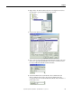
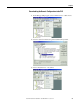
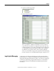
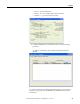
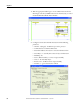
2. Configure General tab in the MSG instruction with the following
parameters:
• Channel: 1 (Integral) - the Ethernet port on the processor
• Communication Command: CIP Generic
• Data Table Address: the location to write the information from
• Size in Bytes: 1 – assembly 101 consists of 1 byte of information
• MultiHop: Yes
• Service: Write Assembly – to write an output assembly
• Class: 4 – the Assembly Object
• Instance: 101 – the Basic Contact output assembly
• Attribute: 3 – get/set data instance attribute