
Manual


76 Rockwell Automation Publication 750COM-UM004B-EN-P - September 2012
Appendix B Option Module Parameters
About Parameter Numbers
Each parameter set is numbered consecutively.
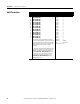
How Parameters Are
Organized
The Device Parameters and Host Parameters are separately displayed in a
Numbered List view order.
Device Parameters
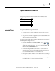
Configuration Tool Numbering Scheme
• HIM
• Connected Components Workbench
software
• DriveExplorer software
• DriveExecutive software
The Device parameters and Host parameters begin with
parameter 01. For example, Device Parameter 01 -
[DPI Port] and Host Parameter 01 - [Net to Drv DL
01] are Parameter 1 as indicated by this manual.
• Acyclic Messaging See Chapter
6, Acyclic Messaging.
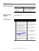
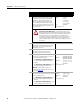
Parameter
No. Name & Description Details
01 [Port Number]
Displays the drive port into which the option
module is installed. Typically, this will be Port 4, 5,
or 6.
Minimum: 0
Maximum: 7
Type: Read Only
02 [DLs From Net Act]
Displays the number of controller-to-drive
Datalinks that the drive is using based on the I/O
connection opened by the controller.
Minimum: 0
Maximum: 16
Type: Read Only
03 [DLs To Net Act]
Displays the number of drive-to-controller
Datalinks that the controller is using based on the
I/O connection opened by the controller.
Minimum: 0
Maximum: 16
Type: Read Only
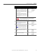
04 [Net Addr Src]
Displays the source from which the option
module’s node address is taken. This will be the
Node Address switches (see Figure 1 on page 20
and Table 1 on page 21
), or the value of Device
Parameter 05 - [Net Addr Cfg].
Values: 0 = Switches
1 = Parameters
Type: Read Only
05 [Net Addr Cfg]
Sets the network node address for the option
module if Device Parameter 04 - [Net Addr Src]
is set to ‘1’ (Parameters).
Default: 126
Minimum: 0
Maximum: 126
Type: Read/Write
06 [Net Addr Act]
Displays the actual network node address used by
the option module.
Minimum: 0
Maximum: 126
Type: Read Only