User Manual PowerFlex 20-COMM-L LonWorks Adapter FRN 1.
Important User Information Read this document and the documents listed in the additional resources section about installation, configuration, and operation of this equipment before you install, configure, operate, or maintain this product. Users are required to familiarize themselves with installation and wiring instructions in addition to requirements of all applicable codes, laws, and standards.
Summary of Changes The information below summarizes the changes made to this manual since its last release (January 2003): Description of Changes Page Reformatted document from half size (5.5 x 8.5 in.) to full size (8.5 x 11 in.). Throughout manual Revised Figures 2.2 and 2.3 to show PowerFlex 700H and PowerFlex 700S Frames 9 and larger. Added ground tab details in Figure 2.
soc-ii Summary of Changes 20-COMM-L LonWorks Adapter User Manual Publication 20COMM-UM008B-EN-P
Table of Contents Preface About This Manual Conventions Used in This Manual . . . . . . . . . . . . . . . . . . . . . . . . . . . . . . . . . . . . . . . . . . P-1 Rockwell Automation Support . . . . . . . . . . . . . . . . . . . . . . . . . . . . . . . . . . . . . . . . . . . . . P-2 Related Documentation . . . . . . . . . . . . . . . . . . . . . . . . . . . . . . . . . . . . . . . . . . . . . . . . . . P-2 Chapter 1 Getting Started Components. . . . . . . . . . . . . . . . . . . . . . . . . . . . . . .
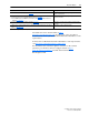
ii Table of Contents Appendix A Specifications Communications . . . . . . . . . . . . . . . . . . . . . . . . . . . . . . . . . . . . . . . . . . . . . . . . . . . . . . . . Electrical . . . . . . . . . . . . . . . . . . . . . . . . . . . . . . . . . . . . . . . . . . . . . . . . . . . . . . . . . . . . . . Mechanical. . . . . . . . . . . . . . . . . . . . . . . . . . . . . . . . . . . . . . . . . . . . . . . . . . . . . . . . . . . . . Environmental . . . . . . . . . . . . . . . . . . . . . . . . . . .
Preface About This Manual Topic Page Related Documentation P-2 Rockwell Automation Support P-2 Conventions Used in This Manual P-1 This manual provides information about the adapter and using it with PowerFlex 7-Class (Architecture-Class) drives. The adapter can be used with other products that support a DPI™ adapter. See the documentation for your product for specific information about how it works with the adapter.
P-2 About This Manual Rockwell Automation Support Rockwell Automation offers support services worldwide, with over 75 sales and support offices, over 500 authorized distributors, and over 250 authorized systems integrators located throughout the United States alone. In addition, Rockwell Automation representatives are in every major country in the world. Local Product Support Contact your local Rockwell Automation, Inc.
About This Manual P-3 Resource Description PowerFlex 700L User Manual, publication 20L-UM001 Information on installing and programming PowerFlex 700L Liquid-Cooled AC drives. PowerFlex 750-Series Drive Installation Instructions, publication 750-IN001 PowerFlex 750-Series Drive Programming Manual, publication 750-PM001 20-750-20COMM and 20-750COMM-F1 Communication Carrier Cards Installation Instructions, publication 750COM-IN001 Information on installing and programming PowerFlex 750-Series AC drives.
P-4 About This Manual Notes: 20-COMM-L LonWorks Adapter User Manual Publication 20COMM-UM008B-EN-P
Chapter 1 Getting Started The adapter is intended for installation into a PowerFlex 7-Class drive and is used for network communication. When used with PowerFlex 750-Series drives, the 20-COMM-L adapter must have firmware revision 1.007 or later, and must be installed using the 20-750-20COMM or 20-750-20COMM-F1 Communication Carrier Card. There are operating limitations and this manual does not include information on using the 20-COMM-L adapter with PowerFlex 750-Series drives.
1-2 Getting Started Features The features of the adapter include the following: • Typical mounting in a PowerFlex 7-Class drive. • Captive screws to secure and ground the adapter to the drive. • Compatibility with various configuration tools to configure the adapter and connected host drive, including the following tools: – – – – PowerFlex HIM (Human Interface Module) on the drive, if available Connected Components Workbench software, version 1.02 or later DriveExplorer software, version 2.
Getting Started Compatible Products 1-3 At the time of publication, the adapter is compatible with the following products: • PowerFlex 70 drives with standard or enhanced control • PowerFlex 750-Series drives (1) • PowerFlex 700 drives with standard or vector control • PowerFlex Digital DC drives • PowerFlex 700H drives • SMC™ Flex smart motor controllers • PowerFlex 700S drives with Phase I or Phase II control • SMC-50 smart motor controllers • PowerFlex 700L drives with 700 vector control or 70
1-4 Getting Started User-Supplied Equipment To install and configure the adapter, you must supply the following: ❑ A small flathead screwdriver ❑ Network-specific cable to connect the adapter to the network. See the network-specific documentation for the cable recommendations and requirements. ❑ Drive and adapter configuration tool, such as the following: – PowerFlex 20-HIM-xx HIM – Connected Components Workbench software, version 1.
Getting Started Safety Precautions 1-5 Please read the following safety precautions carefully. ! ! ! ! ! ! ! ATTENTION: Risk of injury or death exists. The PowerFlex drive can contain high voltages that can cause injury or death. Remove all power from the PowerFlex drive, and then verify power has been discharged before installing or removing an adapter. ATTENTION: Risk of injury or equipment damage exists.
1-6 Getting Started ! ! Quick Start ATTENTION: Risk of injury or equipment damage exists. When a system is configured for the first time, there can be unintended or incorrect machine motion. Disconnect the motor from the machine or process during initial system testing. ATTENTION: Risk of injury or equipment damage exists. The examples in this publication are intended solely for purposes of example. There are many variables and requirements with any application.
Chapter 2 Installing the Adapter This chapter provides instructions for installing the adapter in a PowerFlex 7-Class drive. Topic Page Preparing for an Installation 2-1 Connecting the Adapter to the Drive 2-1 Connecting the Adapter to the Network 2-4 Applying Power 2-5 Preparing for an Installation Before installing the adapter, verify that you have all required equipment. See Required Equipment on page 1-3. ! Connecting the Adapter to the Drive ! ATTENTION: Risk of equipment damage exists.
2-2 Installing the Adapter Important: Tighten all screws to properly ground the adapter. Recommended torque is 0.9 N•m (8.0 lb•in). Figure 2.1 DPI Ports and Internal Interface Cables 20-COMM-L Adapter ➊ ➋ ➌ PowerFlex 70 - All Frames ➍ PowerFlex 700 Frames 0 and 1 PowerFlex 700S Frames 0 and 1 PowerFlex 700 Frames 2 and Larger PowerFlex 700S Frames 2 through 6 HIM panel opens for access to the DPI interface. To open HIM panel, remove screws on left side of HIM panel and swing open.
Installing the Adapter Figure 2.2 2-3 Mounting and Grounding the Adapter Drive 0.9 N•m (8.0 lb•in) 4 Places Adapter Internal Interface Cable folded behind the adapter and in front of the drive. Ground Tab Detail PowerFlex 70 - All Frame Sizes (Adapter mounts in drive.) 0.9 N•m (8.0 lb•in) 4 Places PowerFlex 700 Frames 0 and 1 PowerFlex 700S Frames 0 and 1 (Adapter mounts on door.) Verify metal ground tab is bent 90° and is under the adapter before tightening screw.
2-4 Installing the Adapter Connecting the Adapter to the Network ATTENTION: Risk of injury or death exists. The PowerFlex drive can contain high voltages that can cause injury or death. Remove power from the drive, and then verify power has been discharged before installing or removing the adapter. ! 1. Remove power from the drive. 2. Use static control precautions. 3. Route the LonWorks cable from the network through the bottom of the PowerFlex drive (see Figure 2.2).
Installing the Adapter Applying Power ! 2-5 ATTENTION: Risk of equipment damage, injury, or death exists. Unpredictable operation can occur if you fail to verify that parameter settings are compatible with your application. Verify that settings are compatible with your application before applying power to the drive. Install the drive cover or close the drive door, and apply power to the drive. The adapter receives its power from the connected drive.
2-6 Installing the Adapter Table 2.A Drive and Adapter Start-Up Status Indications Item Name Color State Description Drive STS Indicator ➊ STS (Status) Green Yellow Red Flashing Drive ready but not running, and no faults are present. Steady Drive running, no faults are present. Flashing, drive stopped An inhibit condition exists – the drive cannot be started. Check drive Parameter 214 - [Start Inhibits]. Flashing, drive running An intermittent type 1 alarm condition is occurring.
Installing the Adapter 2-7 3. Verify that drive Parameter 213 - [Speed Ref Source] is reporting that the source of the Reference to the drive is ‘22’ (DPI Port 5). This ensures that any Reference commanded from the network can be monitored by using drive Parameter 002 - [Commanded Speed]. If a problem occurs, this verification step provides the diagnostic capability to determine whether the drive/adapter or the network is the cause.
2-8 Installing the Adapter Notes: 20-COMM-L LonWorks Adapter User Manual Publication 20COMM-UM008B-EN-P
Chapter 3 Configuring the Adapter This chapter provides instructions and information for setting the parameters to configure the adapter.
3-2 Configuring the Adapter Using the PowerFlex 7-Class If your drive has either an LED or LCD HIM (Human Interface Module), it can be used to access parameters in the adapter as shown below. We HIM to Access Parameters recommend that you read through the steps for your HIM before performing the sequence. For additional information, see the drive documentation or the PowerFlex 7-Class HIM Quick Reference, publication 20HIM-QR001. Using an LED HIM Step Example Screens 1.
Configuring the Adapter Setting the I/O Configuration 3-3 The I/O configuration determines the data that is sent to and from the drive. Logic Command/Status, Reference/Feedback, and Datalinks may be enabled or disabled. (Datalinks allow you to read/write directly to parameters in the drive using implicit I/O.) A ‘1’ enables the I/O and a ‘0’ disables the I/O. 1. Set the bits in Parameter 9 - [DPI I/O Cfg].
3-4 Configuring the Adapter Setting a Communication Fault Action By default, when I/O communication is disrupted (for example, a cable is disconnected), the drive responds by faulting if it is using I/O from the network. You can configure a different response to the disrupted I/O communication by using Parameter 6 - [Comm Flt Action]. The drive will remain in its present state (for example, a running drive will continue to run) until the value in Parameter 7 - [RcvHrtBeat Time] has elapsed.
Configuring the Adapter Port 5 Device 20-COMM-L Parameter #: 07 RcvHrtBeat Time 120.0 s 0 <> 3276.7 3-5 Default = 120.0 s Changes to these parameters take effect immediately. A reset is not required. Setting the Fault Configuration Parameters When setting Parameter 6 - [Comm Flt Action] or 8 - [Idle Flt Action] to ‘Send Flt Cfg’, the values in the following parameters are sent to the drive after an I/O communication fault and/or idle fault occurs.
3-6 Configuring the Adapter Setting the Fault Configuration Parameters See Setting the Fault Configuration Parameters on page 3-5 for details, which apply to both Parameter 6 - [Comm Flt Action] and Parameter 8 [Idle Flt Action]. Resetting the Adapter Changes to some adapter parameters require that you reset the adapter before the new settings take effect. You can reset the adapter by power cycling the drive or by using Parameter 5 - [Reset Module].
Configuring the Adapter Updating the Adapter Firmware 3-7 The adapter firmware can be updated over the network or serially through a direct connection from a computer to the drive using a 1203-USB or 1203-SSS serial converter. When updating firmware over the network, you can use the Allen-Bradley ControlFLASH software tool, the built-in update capability of DriveExplorer Lite or Full software, or the built-in update capability of DriveExecutive software.
3-8 Configuring the Adapter Notes: 20-COMM-L LonWorks Adapter User Manual Publication 20COMM-UM008B-EN-P
Chapter 4 Configuring the LonWorks Network This chapter provides information about configuring network variables to access a PowerFlex 7-Class drive over a LonWorks network.
4-2 Configuring the LonWorks Network Operating the Drive Using a A LonMark profile defines the functional profile for a node communicating with other nodes. The profile specifies which SNVTs (Standard Network LonMark Profile Variable Types) and SCPTs (Standard Configuration Property Types) are used, and provides a semantic meaning about the information being communicated. When a profile is implemented in a node, it is called a LonMark object. One node can have several objects implemented.
Configuring the LonWorks Network Figure 4.
4-4 Configuring the LonWorks Network Node Operations The following sections describe the basics of node operation. WINK (What is a WINK?) WINK is a network command that verifies communication with a node. The NET A status indicator flashes to indicate that a WINK was received. This LED flashes red according to the following sequence: • 3 fast flashes • OFF for 1 second This sequence is repeated 10 times.
Configuring the LonWorks Network Network Variable Inputs (NVIs) 4-5 This section provides descriptions of the Network Variable Inputs. Node Object Request Variable: nviObjRequest Format: SNVT_obj_request Explanation: This input enables control commands and updates from the network to specific objects in the node. The identification number for the node is 0 and for the drive object is 1. The request functionality is the same for both objects.
4-6 Configuring the LonWorks Network Drive Speed Setpoint Variable: nviDrvSpeedStpt Format: SNVT_switch Explanation: This network variable input provides a speed reference setpoint. When nviDrvSpeedStpt.state is set to zero, the drive is stopped. Valid Range: State Value Requested Speed 0 n/a STOPPED 1 0% 0% 1 0.5…100.0% 0.5…100.0% 1 100.0% 100.0% 0xFF n/a AUTO (Default) Default Value: Default value is AUTO (state = 0xFF). This value is adapted at power up.
Configuring the LonWorks Network 4-7 Module Configuration Variable: nviNV_config Format: UNVT_DPI_CONFIG Explanation: This network variable input provides information on how parameters should be mapped to network variables. The NVI contains two fields: • NV_index • DPI_parameter To check an already existing configuration, use the following procedures: A. To check which DPI parameter a network variable is connected to, use nviNV_config with the following data: UNVT_DPI_CONF.
4-8 Configuring the LonWorks Network Default Value: This configuration is the default for PowerFlex 70/700 drives. For other drives, the defaults are 0 and need to be configured prior to network commissioning. A value of 0 means the variable is disabled and cannot be used to send/receive data. Note: It is necessary to configure nciNmlFreq and nciMaxSpeed to operate the drive from the network.
Configuring the LonWorks Network Network Variable Outputs (NVOs) 4-9 This section describes the network variable outputs. No output values are sent over the network, unless they have changed (except nvoDrvSpeed, which is sent for the heartbeat functionality, and nvoObjStatus, if update status is requested).
4-10 Configuring the LonWorks Network Drive Speed Variable: nvoDrvSpeed Format: SNVT_level_percent Explanation: This network variable output provides the speed of the drive as a percentage of the nominal speed. This network variable output is also used as a heartbeat to monitor the health of the LonWorks communication interface. Default PowerFlex 70/700 Drive Parameter Mapping: Parameter 1 - [Output Freq] This can be mapped using the nviNV_config variable.
Configuring the LonWorks Network 4-11 Output Frequency Variable: nvoDrvFreqAct Format: SNVT_freq_hz Explanation: This network variable output provides the drive output frequency in Hz. This value is always positive. It does not indicate the forward/reverse direction of motor revolution. Default PowerFlex 70/700 Drive Parameter Mapping: Parameter 1 - [Output Freq] This can be mapped using the nviNV_config variable or adapter Parameter 28 - [DrvFreqActParam].
4-12 Configuring the LonWorks Network Datalink Outs Variable: nvoDatalinkA1 nvoDatalinkA2 nvoDatalinkB1 nvoDatalinkB2 nvoDatalinkC1 nvoDatalinkC2 nvoDatalinkD1 nvoDatalinkD2 Format: UNVT_DATALINK Explanation: These network variable outputs are used for generic parameter inputs by way of Datalink Outs. To set up a Datalink, configure the adapter according to the drive manual. All data is sent in raw format; that is, no scaling is performed.
Configuring the LonWorks Network Network Configuration Inputs (NCIs) 4-13 The values of the NCIs change when written to and keep their values after a power cycle. All NCIs, with a corresponding parameter in the drive, are read from the drive after reset and when going from offline to online. When the parameter is updated from the network, it is written to the drive.
4-14 Configuring the LonWorks Network Minimum Send Time NCI: nciMinOutTm Format: SNVT_time_sec Explanation: This network configuration input specifies the minimum period of time that expires before the network variable outputs can be re-sent. All variables are updated if they changed at each period end. This can help to limit the use of bandwidth on the LonWorks network. Setting nciMinOutTm to ‘0’ disables transmission limiting. Valid Range: 0.0…6553.4 seconds. Default Value: 0.
Configuring the LonWorks Network 4-15 Minimal Speed NCI: nciMinSpeed Format: SNVT_lev_percent Explanation: This network configuration input specifies the minimum speed of the motor. Its value is entered as a percentage of nominal frequency as defined by the Nominal frequency (nciNmlFreq) configuration value. For example, if nciNmlFreq = 50 Hz. and nciMinSpeed = 10%, the minimum speed is 5 Hz. Valid Range: The minimum speed value must be validated as follows: -163.84% ≤ minimum speed ≤ maximum speed ≤ 163.
4-16 Configuring the LonWorks Network Ramp Up Time NCI: nciRampUpTm Format: SNVT_time_sec Explanation: This network configuration input sets the acceleration time. The value specifies the length of time it will take to bring the inverter from stop to maximum frequency. Default Value: 10.0 seconds Default PowerFlex 70/700 Drive Parameter Mapping: Parameter 140 - [Accel Time] This can be adjusted using the nviNV_config variable or adapter Parameter 33 - [RampUpTmParam].
Configuring the LonWorks Network 4-17 Generic Parameter Read Address NCI: nciParRdAdr Format: SNVT_count Explanation: This network configuration input is used to read any parameter in the drive. The data is read via the nvoGenData output. Default Value: 0 (Not used) Valid Range: Any valid drive parameter. Generic Parameter Write Address NCI: nciParWriAdr Format: SNVT_count Explanation: This network configuration input is used to set the parameter number to which a write operation is to be performed.
4-18 Configuring the LonWorks Network Conditions Required for Operation This section describes what conditions are required for performing some common actions and how the combination of SNVTs and SCPTs affects the operation of the drive. Starting the Drive The drive will RUN if nviDrvSpeedStpt.state is TRUE. Stopping the Drive The drive stops using the default stop mode if NviSpeedStpt.
Configuring the LonWorks Network 4-19 Error Handling If nciRcvHrtBt is larger than zero, and heartbeats are not received within the nciRcvHrtBt time, then communication with the LonWorks network is considered down. The adapter response to loss of communication depends on the setting of adapter Parameter 6 - [Comm Flt Action]. See Chapter 5, Troubleshooting for more information on potential problems with the adapter and network.
4-20 Configuring the LonWorks Network Notes: 20-COMM-L LonWorks Adapter User Manual Publication 20COMM-UM008B-EN-P
Chapter 5 Troubleshooting This chapter provides information for diagnosing and troubleshooting potential problems with the adapter and network. Understanding the Status Indicators Topic Page Understanding the Status Indicators 5-1 PORT Status Indicator 5-2 MOD Status Indicator 5-2 NET A Status Indicator (Service Indicator) 5-3 Viewing and Clearing Adapter Diagnostic Items 5-3 Viewing and Clearing Events 5-5 The adapter has three status indicators.
5-2 Troubleshooting PORT Status Indicator This red/green bicolor LED indicates the status of the adapter’s connection to the drive as shown in the table below. Status Cause Corrective Action Off The adapter is not powered or is not properly connected to the drive. • Securely connect the adapter to the drive using the Internal Interface (ribbon) cable. Flashing Red The adapter is not receiving a ping message from the drive. Steady Red The drive has refused an I/O connection from the adapter.
5-3 Troubleshooting NET A Status Indicator (Service Indicator) Viewing and Clearing Adapter Diagnostic Items This red/green bicolor LED indicates the status of the network connection as shown in the table below, and is controlled by the Neuron Chip. Status Cause Corrective Actions Off The node is configured. No action required. Flashing Red WINK command received. No action required. Flashing Green The node is not configured. Configure the node.
5-4 Troubleshooting Table 5.A Adapter Diagnostic Items No. Name Description 1 Common Logic Cmd The present value of the Common Logic Command being transmitted to the drive by this adapter. 2 Product Logic Cmd The present value of the Product Logic Command being transmitted to the drive by this adapter. 3 Reference The present value of the Reference being transmitted to the drive by this adapter. Note that a 16-bit value will be sent as the Most Significant Word of the 32-bit field.
5-5 Troubleshooting Viewing and Clearing Events The adapter has an event queue to record significant events that occur in the operation of the adapter. When such an event occurs, an entry is put into the event queue. You can view the event queue with any of these drive configuration tools: • • • • LCD PowerFlex 7-Class HIM Connected Components Workbench software, version 1.02 or later DriveExplorer software, version 2.01 or later DriveExecutive software, version 1.
5-6 Troubleshooting Events Many events in the event queue occur under normal operation. If you encounter unexpected communications problems, the events may help you or Allen-Bradley personnel troubleshoot the problem. The following events may appear in the event queue. Table 5.B Adapter Events Code Event Description 1 No Event Empty event queue entry. 2 DPI Bus Off Flt A bus-off condition was detected on DPI. This event may be caused by loose or broken cables or by noise.
Appendix A Specifications This appendix presents the specifications for the adapter. Communications Electrical Mechanical Environmental Topic Page Communications A-1 Electrical A-1 Mechanical A-1 Environmental A-1 Regulatory Compliance A-2 Network Protocol Data Rate LonWorks 78 kbps Drive Protocol Data Rates DPI 125 kbps or 500 kbps Consumption Drive Network 200 mA at 5V DC supplied by the host drive None Dimensions Height Length Width 20 mm (0.79 inches) 86 mm (3.39 inches) 78.
A-2 Specifications Regulatory Compliance Certification Specification UL UL508C cUL CAN / CSA C22.2 No. 14-M91 CE EN50178 and EN61800-3 CTick EN61800-3 NOTE: This is a product of category C2 according to IEC 61800-3. In a domestic environment this product may cause radio interference in which case supplementary mitigation measures may be required.
Appendix B Adapter Parameters Appendix B provides information about the adapter parameters. Topic About Parameter Numbers Parameter List About Parameter Numbers The parameters in the adapter are numbered consecutively. Configuration Tool • HIM • DriveExplorer • DriveExecutive Parameter List Page B-1 B-1 Numbering Scheme The adapter parameters begin with parameter 01. For example, Parameter 01 - [DPI Port] is parameter 01 as indicated by this manual. Parameter No.
B-2 Adapter Parameters Parameter No. Name and Description 06 [Comm Flt Action] Details Default: Values: 0 = Fault 0 = Fault Sets the action that the adapter and drive takes if the 1 = Stop adapter detects that network communication has been 2 = Zero Data disrupted (if Parameter 7 - [RcvHrtBeat Time] times 3 = Hold Last out before nviDrvSpeedStpt is updated from the 4 = Send Flt Cfg network). This setting is effective only if I/O that Read/Write controls the drive is transmitted through the adapter.
B-3 Adapter Parameters Datalink D Datalink C Datalink B Datalink A Cmd/Ref x 6 x 5 0 4 0 3 0 2 0 1 1 0 Default: Bit Values: xxx0 0001 0 = I/O disabled 1 = I/O enabled Read Only Datalink A Cmd/Ref Default Bit Datalink B Bit Definition Datalink C Type: Datalink D Displays the I/O that the adapter is actively transmitting. The value of this parameter is usually equal to the value of Parameter 9 - [DPI I/O Cfg].
B-4 Adapter Parameters Parameter No. Name and Description 21 [Send Service Pin] Broadcasts a LON Service Pin Message from the Neuron Chip. This provides the Neuron ID. Details Default: Values: 0 = Ready 0 = Ready 1 = Send Type: Read/Write Reset Required: No An alternate method for providing the Neuron ID is to enter the ID number manually. The Neuron ID can be viewed using Diagnostic Item # 30 (see page 5-4).
Adapter Parameters Parameter No. Name and Description 30 [NmlSpeedParam] Details Default: Sets the PowerFlex 7-Class drive parameter number to Values: be used with nciNmlSpeed (see page 4-14). Type: Reset Required: 31 [MaxSpeedParam] Default: Sets the PowerFlex 7-Class drive parameter number to Values: be used with nciMaxSpeed (see page 4-15). Type: Reset Required: 32 [MinSpeedParam] Default: Sets the PowerFlex 7-Class drive parameter number to Values: be used with nciMinSpeed (see page 4-15).
B-6 Adapter Parameters Notes: 20-COMM-L LonWorks Adapter User Manual Publication 20COMM-UM008B-EN-P
Appendix C Logic Command/Status Words This appendix presents the definitions of the Logic Command and Logic Status words that are used for some products that can be connected to the adapter. If the Logic Command/Logic Status for the product that you are using is not listed, refer to your product’s documentation.
C-2 Logic Command/Status Words Logic Status Word Logic Bits 15 14 13 12 11 10 9 8 7 6 5 4 3 2 x x x x x x x x x (1) x x x x x See ‘Owners’ in the drive User Manual for more information. 20-COMM-L LonWorks Adapter User Manual Publication 20COMM-UM008B-EN-P 1 0 Status x Ready x Active Command Direction Actual Direction Accel Decel Alarm Fault At Speed Local Control (1) Reference Description 0 = Not Ready (Par.
Logic Command/Status Words PowerFlex 700S Drives C-3 Logic Command Word (Phase II Control) Logic Bits 15 14 13 12 11 10 9 8 7 6 5 4 3 2 x x x x x x x x x x x x x x 1 0 Command x Normal Stop x Start (1) Jog 1 Clear Fault (2) Unipolar Direction Description 0 = Not Normal Stop 1 = Normal Stop 0 = Not Start 1 = Start 0 = Not Jog using [Jog Speed 1] (Par. 29) 1 = Jog using [Jog Speed 1] (Par.
C-4 Logic Command/Status Words Logic Status Word (Phase II Control) Logic Bits 15 14 13 12 11 10 9 8 7 6 5 4 3 2 1 x x x x x x x x x x x x x x x (1) 0 Status x Active Running Command Direction Actual Direction Accel Decel Jogging Fault Alarm Flash Mode Run Ready At Limit (1) Tach Loss Sw At Zero Spd At Setpt Spd Enable Description 0 = Not Active 1 = Active 0 = Not Running 1 = Running 0 = Reverse 1 = Forward 0 = Reverse 1 = Forward 0 = Not Accelerating 1 = Accelerating 0 = Not Decelerating 1 = D
Logic Command/Status Words C-5 PowerFlex 750-Series Drives Important: When using a 20-COMM-L adapter with a PowerFlex 750-Series drive, the upper word (bits 16…31) of the Logic Command and Logic Status words are not accessible and cannot be used. Only when using a PowerFlex 750-Series drive with a 20-750 communication Option Module (or the PowerFlex 755 drive’s embedded EtherNet/IP adapter) is the upper word accessible and used.
C-6 Logic Command/Status Words Logic Status Word Logic Bits 31…15 14 13 12 11 10 9 8 7 6 5 4 3 2 1 x x x x x x x x x x x x x x x 20-COMM-L LonWorks Adapter User Manual Publication 20COMM-UM008B-EN-P 0 Command x Run Ready Active Command Direction Actual Direction Accelerating Decelerating Alarm Fault At Setpt Spd Manual Spd Ref ID 0 Spd Ref ID 1 Spd Ref ID 2 Spd Ref ID 3 Spd Ref ID 4 Reserved Description 0 = Not Ready to Run (Par.
Glossary A Adapter Devices such as drives, controllers, and computers usually require a network communication adapter to provide a communication interface between them and a network such as LonWorks. An adapter reads data on the network and transmits it to the connected device. It also reads data in the device and transmits it to the network. The 20-COMM-L LonWorks adapter connects PowerFlex 7-Class drives to a LonWorks network.
G-2 Glossary D Data Rate The speed at which data is transferred on the network. Each device on the network must be set for the same data rate. Datalinks A Datalink is a type of pointer used by PowerFlex 7-Class drives to transfer data to and from the controller. Datalinks enable specified parameters to be read or written to without using explicit messages. The drive determines the size of Datalinks.
Glossary F G-3 Fault Action A fault action determines how the adapter and connected drive act when a communication fault (for example, a cable is disconnected) occurs. Fault Configuration When communication is disrupted (for example, a cable is disconnected), the adapter and connected drive can respond with a user-defined fault configuration. The user sets the data that is sent to the drive using specific fault configuration parameters in the adapter.
G-4 Glossary LON™ An acronym for local operating network. Consists of intelligent devices, or nodes, that are connected by one or more communications media and that communicate with one another using a common protocol. LonMaker™ Software Windows™-based software package for designing, documenting, installing, and maintaining multi-vendor, open, interoperable LonWorks networks. LonWorks™ Device Hardware and software than runs an application and communicates with other devices using the LonWorks protocol.
Glossary P G-5 Ping A message that is sent by a DPI product to its peripheral devices. They use the ping to gather data about the product, including whether it can receive messages and whether they can log in for control. PowerFlex 7-Class (Architecture Class) Drives The Allen-Bradley PowerFlex 7-Class family of drives supports DPI and, at the time of publication, includes the PowerFlex 70, PowerFlex 700, PowerFlex 700H, PowerFlex 700S, PowerFlex 700L, and PowerFlex 7000.
G-6 Glossary Type 0/Type 1/Type 2 Control When transmitting I/O, the adapter can use different types of messages for control. The Type 0, Type 1, and Type 2 events help Rockwell Automation personnel identify the type of message that is used. 20-COMM-L LonWorks Adapter User Manual Publication 20COMM-UM008B-EN-P U Update The process of updating firmware in a device. The adapter can be updated using various Allen-Bradley software tools. See Updating the Adapter Firmware on page 3-7 for more information.
Index A adapter applying power, 2-5 compatible products, 1-3 components, 1-1 configuration tools, 3-1 connecting to the drive, 2-1 network, 2-4 definition, G-1 features, 1-2 firmware updating, 3-7 grounding, 2-3 installation, 2-1 to 2-7 mounting on the drive, 2-3 parameters, B-1 to B-5 resetting, 3-6 specifications, A-1 viewing its status, 3-6 applying power to the adapter, 2-5 attentions, 1-5 B baud rate, see data rate binding, definition of, G-1 bit definitions of Logic Command/Status word for PowerFlex
Index-2 DrvPwrParam parameter, B-4 DrvRunHoursParam parameter, B-4 DrvSpeedParam parameter, B-4 DrvVoltParam parameter, B-4 I I/O configuring the adapter for, 3-3 definition, G-3 Idle Flt Action parameter, B-2 E EEPROM, see Nonvolatile Storage (NVS) environmental specifications, A-1 equipment required, 1-3 events clearing/viewing, 5-5 list of, 5-6 F fault action configuring the adapter for, 3-4, 3-5 definition, G-3 installation applying power to the adapter, 2-5 connecting to the drive, 2-1 network, 2-
Index-3 MinSpeedParam parameter, B-5 MOD status indicator locating, 5-1 troubleshooting with, 5-2 Module Configuration (NVI), 4-7 mounting the adapter, 2-3 N PORT status indicator locating, 5-1 troubleshooting with, 5-2 power consumption, A-1 PowerFlex drives compatible with adapter, 1-3 definition, G-5 HIM, 3-2 installing adapter on, 2-1 NCIs (Network Configuration Inputs), 4-13 preparing for an installation, 2-1 NET A status indicator locating, 5-1 troubleshooting with, 5-3 protocols, definition of
Index-4 T technical support, P-2 tools required, 1-3 transceiver, definition of, G-5 troubleshooting, 5-1 to 5-6 U update definition, G-6 guidelines, 3-7 W website for Connected Components Workbench software, G-1 DriveExecutive software, G-2 DriveExplorer software, G-2 DriveTools SP software, G-2 related documentation, P-2 wiring, see cables Z zero data configuring the adapter for, 3-4, 3-5 definition, G-6 20-COMM-L LonWorks Adapter User Manual Publication 20COMM-UM008B-EN-P
Rockwell Automation Support Rockwell Automation provides technical information on the Web to assist you in using its products. At http://www.rockwellautomation.com/support you can find technical and application notes, sample code, and links to software service packs. You can also visit our Support Center at https://rockwellautomation.custhelp.com/ for software updates, support chats and forums, technical information, FAQs, and to sign up for product notification updates.