User Manual Micro800 Discrete and Analog Expansion I/O Catalog Numbers Bulletin 2085
Important User Information Solid-state equipment has operational characteristics differing from those of electromechanical equipment. Safety Guidelines for the Application, Installation and Maintenance of Solid State Controls (publication SGI-1.1 available from your local Rockwell Automation sales office or online at http://www.rockwellautomation.com/literature/) describes some important differences between solid-state equipment and hard-wired electromechanical devices.
Preface Read this preface to familiarize yourself with the rest of the manual. It provides information concerning: • who should use this manual • the purpose of this manual • related documentation • supporting information for Micro800™ Who Should Use this Manual Use this manual if you are responsible for designing, installing, programming, or troubleshooting control systems that use Micro800 controllers. You should have a basic understanding of electrical circuitry and familiarity with relay logic.
Preface Resource Description Micro800 8-Point Input and 8-Point Output AC Modules Installation Instructions 2085-IN005 Information on mounting and wiring the expansion I/O modules (2085-IA8, 2085-IM8, 2085-OA8) Micro800 4-channel and 8-channel Analog Voltage/current Input and Output Modules Installation Instructions 2085-IN006 Information on mounting and wiring the expansion I/O modules (2085-IF4, 2085-IF8, 2085-OF4) Micro800 4-channel Thermocouple/RTD Input Module 2085-IN007 Information on mounting
Preface Notes: Rockwell Automation Publication 2080-UM003A-EN-E - March 2013 v
Preface vi Rockwell Automation Publication 2080-UM003A-EN-E - March 2013
Table of Contents Preface Who Should Use this Manual . . . . . . . . . . . . . . . . . . . . . . . . . . . . . . . . . . . . . . iii Purpose of this Manual . . . . . . . . . . . . . . . . . . . . . . . . . . . . . . . . . . . . . . . . . . . . iii Additional Resources . . . . . . . . . . . . . . . . . . . . . . . . . . . . . . . . . . . . . . . . . . . . . . iii Chapter 1 Hardware Features Micro800 Expansion I/O Modules . . . . . . . . . . . . . . . . . . . . . . . . . . . . . . . . . .
Table of Contents Appendix B Expansion I/O Data Mapping Discrete I/O Data Mapping . . . . . . . . . . . . . . . . . . . . . . . . . . . . . . . . . . . . . . . Analog I/O Data Mapping . . . . . . . . . . . . . . . . . . . . . . . . . . . . . . . . . . . . . . . . Specialty I/O Data Mapping. . . . . . . . . . . . . . . . . . . . . . . . . . . . . . . . . . . Calibration of Analog Modules . . . . . . . . . . . . . . . . . . . . . . . . . . . . . . . . . . . . Specifications . . . . . . . . . . . . . . . . .
Chapter 1 Hardware Features Micro850 controllers support a range of discrete and analog expansion I/O modules. You can attach up to four expansion I/O modules, in any combination, to a Micro850 controller, as long as the total number of embedded, plug-in, and expansion discrete I/O points is less than or equal to 132.
Chapter 1 Hardware Features Micro800 Expansion I/O Modules Catalog Type Description 2085-OF4 Analog 4-channel, 12-bit isolated(1) voltage/current output 2085-IRT4 Analog 4-channel, 16-bit isolated(1) RTD and Thermocouple input module 2085-ECR Terminator 2085 bus terminator (1) Refers to isolation from field side wiring to controller, not channel-to-channel isolation. The bus terminator, 2085-ECR, serves as an end cap and terminates the end of the serial communication bus.
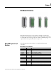
Hardware Features Chapter 1 Double-width Expansion I/O 2 2085-OW16 shown 1 3 6 3 4 8 7 5 3 6 1 9 45296 1 45297 Front view Right top view Module Description Description Description 1 Mounting screw hole / mounting foot 6 Bus connector (male/female) 2 Removable Terminal Block (RTB)(1) 7 Latch hooks 3 RTB hold down screws 8 I/O status LED 4 Cable grip 9 DIN rail mounting latch 5 Module interconnect latch (1) The removable terminal block has slots for mechanical keying, to preve
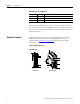
Chapter 1 Hardware Features 2085-IQ32T Hardware Components Description Summary 4 Description 1 Mounting screw hole / mounting foot 6 bus connector (male and female) 2 Connector 7 latch hooks 3 Connector retaining arm 8 I/O status LEDs 4 Cable grip 9 DIN rail mounting latch 5 Module interconnecting latch This chapter included a brief introduction to the different analog and discrete Micro800 expansion I/O modules and their hardware features.
Chapter 2 Discrete and Analog Expansion I/O Features Overview Discrete Expansion I/O Features This section includes a brief description of the different features and configuration parameters for the analog and discrete Micro800 expansion I/O modules. It covers the following topics.
Chapter 2 Discrete and Analog Expansion I/O Features The 2085-IA8, 2085-IM8, 2085-IQ16 and 2085-IQ32T modules update the controller with new data whenever an input point transitions from On to Off and Off to On. On to Off and Off to On filter times can be adjusted through the Connected Components Workbench software. These filters improve noise immunity within a signal. A larger filter value affects the length of delay times for signals from these modules.
Discrete and Analog Expansion I/O Features Chapter 2 Micro800 Expansion I/O Modules Catalog Type Description 2085-OF4 Analog 4-channel, 12-bit isolated(1) voltage/current output 2085-IRT4 Analog 4-channel, 16-bit isolated(1) RTD and Thermocouple input module 2085-ECR Terminator 2085 bus terminator (1) Refers to isolation from field side wiring to controller, not channel-to-channel isolation.
Chapter 2 Discrete and Analog Expansion I/O Features • Engineering Units – The module scales the analog input data to the actual current or voltage values for the selected input range. The resolution of the engineering units is 0.001V or 0.001 mA per count. • Percent Range – The input data is presented as a percentage of the normal operating range. For example, 0V…10V DC equals 0…100%. The amount over and under the normal operating range (the full-scale range) is also supported.
Discrete and Analog Expansion I/O Features Chapter 2 Convert Analog Value to Data Format Value The formula for converting an analog value x to a data format value y (or conversely, deriving data format value y to analog value x) is as follows: Y = ((X - Minimum Value of X Range)*(Range of Y)/(Range of X)) + (Minimum Value of Y Range) Example 1: Find the analog value Y of Type/Range 4…20 mA when the Raw/Proportional Data X is -20000.
Chapter 2 Discrete and Analog Expansion I/O Features • 4-Point Moving Average • 8-Point Moving Average Noise Rejection The input modules use a digital filter that provides noise rejection for the input signals. The moving average filter reduces the high frequencies and random white noise while keeping an optimal step response. (See specifications for Analog Expansion I/O on page 50 for minimum and maximum response times.
Discrete and Analog Expansion I/O Features Chapter 2 The following table shows the default values of the High/Low Clamps (in the order of low clamp value followed by the high clamp value) for the respective type/range when they are first enabled. You can change these values (within their full range) according to your application.
Chapter 2 Discrete and Analog Expansion I/O Features Supported RTD Types and Ohms Range Sensor Range Range 100 Ω Nickel 618 -60…250 °C (-76…482 °F) 200 Ω Nickel 618 -60…200 °C (-76…392 °F) 120 Ω Nickel 672 -80…260 °C (-112…500 °F) 10 Ω Copper 427 -200…260 °C (-328…500 °F) Ohms 0…500 Ohms Data format You can configure the following data formats for channels 0…3 through the Connected Components Workbench software.
Discrete and Analog Expansion I/O Features Chapter 2 Valid Range of the 2085-IRT4 Data Formats Data Format Sensor Type – Temperature (10 Thermocouples, 8 RTDs) Raw/Proportional Data(1) Sensor Type 0…100 mV Sensor Type 0…500 ohms -32768…32767 (3) Engineering Units x 1 Temperature Value (°C/°F) 0…10000(5) 0…5000(7) Engineering Units x 10 Temperature Value(4) (°C/°F) 0…1000(6) 0…500(8) Percent Range(2) 0…10000 (1) See Convert Analog Value to Data Format Value on page 13.
Chapter 2 Discrete and Analog Expansion I/O Features Temperature Units Temperature value can be set to °C (default) or °F. Open circuit response This parameter defines the response to be taken by the module during an open circuit. • Upscale – Sets input to full upper scale value of channel data word. The full-scale value is determined by the selected input type, data format, and scaling. • Downscale – Sets input to full lower scale value of channel data word.
Chapter 3 Wiring Connections In solid-state control systems, grounding and wire routing helps limit the effects of noise due to electromagnetic interference (EMI). ATTENTION: Do not wire more than 2 conductors on any single terminal. Input/Output Wiring Basic wiring of devices to the expansion I/O modules are shown below.
Chapter 3 Wiring Connections 2085-IQ16 I-00 I-08 I-01 I-09 COM0 COM1 I-02 I-10 I-03 I-11 COM0 COM1 I-04 I-12 I-05 I-13 COM0 COM1 I-06 I-14 I-07 I-15 COM0 COM1 Terminal Block 1 Terminal Block 2 -DC (sinking) +DC (sourcing) 45299 2085-OA8 L1 O-00 O-01 L1 O-02 O-03 L1 120V / 240V AC O-04 O-05 L1 O-06 O-07 L1 45314 L2 16 Rockwell Automation Publication 2080-UM003A-EN-E - March 2013
Wiring Connections Chapter 3 2085-IQ32T COM0 COM2 COM0 COM2 I-00 I-16 I-01 I-17 I-02 I-18 I-03 I-19 I-04 I-20 I-05 I-21 I-06 I-22 I-07 I-23 I-08 I-24 I-09 I-25 I-10 I-26 I-11 I-27 I-12 I-28 I-13 I-29 I-14 I-30 I-15 I-31 COM1 COM3 COM1 COM3 45300 See Wiring Options for the 2085-IQ32T Module on page 21.
Chapter 3 Wiring Connections 2085-OB16 and 2085-OV16 2085-OB16 2085-OV16 +CM0 +CM1 +CM0 +CM1 O-00 O-08 O-00 O-08 O-01 O-09 O-01 O-09 O-02 O-10 O-02 O-10 O-03 O-11 O-03 O-11 -CM0 -CM1 -CM0 -CM0 O-04 O-12 O-04 O-12 O-05 O-13 O-05 O-13 O-06 O-14 O-06 O-14 O-07 O-15 O-07 O-15 -CM0 -CM1 -CM0 -CM0 NC NC NC NC 24V DC (Source) 24V DC (Sink) 45306 Terminal Block 1 Terminal Block 1 Terminal Block 2 Terminal Block 2 45327 2085-OW8 L1 or +DC or -DC CM0 O-00 O-
Wiring Connections Chapter 3 2085-OW16 L1 or +DC or -DC CM0 CM4 O-00 O-08 O-01 O-09 CM1 CM5 O-02 O-10 O-03 O-11 CM2 CM6 O-04 O-12 O-05 O-13 CM3 CM7 O-06 O-14 O-07 O-15 L2 or -DC or +DC 45311 Terminal Block 1 Terminal Block 2 2085-IF4 CI-0 VI-0 Current transmitter COM0 Shielded cable CI-1 VI-1 Voltage transmitter COM1 Shielded cable CI-2 VI-2 Current transmitter COM2 Shielded cable CI-3 VI-3 Voltage transmitter COM3 Shielded cable Rockwell Automation Publication 2080-U
Chapter 3 Wiring Connections 2085-IF8 CI-0 VI-0 CI-4 Current transmitter COM0 Current transmitter VI-4 COM4 Shielded cable Shielded cable CI-1 VI-1 CI-5 VI-5 Voltage transmitter COM1 Voltage transmitter COM5 Shielded cable Shielded cable CI-2 VI-2 CI-6 Current transmitter COM2 Current transmitter VI-6 COM6 Shielded cable Shielded cable CI-3 VI-3 COM3 CI-7 VI-7 Voltage transmitter Shielded cable Voltage transmitter COM7 Shielded cable 45322 Terminal Block 2 Terminal Block 1 20
Wiring Connections Chapter 3 2085-IRT4 3-wire RTD 2-wire RTD Ohm input 1 1 OR 2 CH0+ CH2+ CH0H CH2H CH0L CH2L CH0- CH2- CH1+ CH3+ CH1H CH3H CH1L CH3L CH1- CH3- NC CJC+ CJC+ NC TH TH NC CJC- CJC- NC NC 1 1a 2 2 Shielded cable Shielded cable 1 1a 2a 2 4-wire RTD Thermocouple 1 2 Shielded cable mV OR Shielded cable Terminal Block 1 If a thermocouple is used, the use of the supplied CJC assembly is compulsory.
Chapter 3 Wiring Connections Option 1 – Wire the Connector with Available 40-pin Connector 2085-IQ32T module Keyed female connector Included with the module. Keyed male connector Contact pins provided with female connector can accept 22...26 AWG wires. User terminal connector Panel buttons, sensors 44924 Assemble the Wire Contacts 1. Strip the wire insulation to expose 4 mm (5/32 in.) of wire. Crimp pins can accept 22...26 AWG wire. ATTENTION: Be careful when stripping wires.
Wiring Connections Chapter 3 6. Insert the assembled wire contact into the terminal socket. Push the wire contact in until the tang latches. Make sure the tang is properly latched by lightly pulling on the wire. Terminal connector Terminal sockets Wire contact 44922 Option 2 – Use Allen-Bradley 1492 Connector Cables with Flying Leads Preassembled 40-conductor cables with the 40-pin connector on one end and flying leads on the other end are also available from Allen-Bradley.
Chapter 3 Wiring Connections Allen-Bradley 1492 wiring systems are available for connecting the I/O module to external I/O. These wiring systems include a pre-wired cable available in four lengths: 0.5m (1.6 feet), 1.0m (3.3 feet), 2.5m (8.2 feet), 5.0m (16.4 feet). An Interface Module for connecting external devices is also available. Cables are equipped with keyed connectors at both ends for proper connections.
Chapter 4 Install Your Micro800 Expansion I/O This chapter includes information on installing the Micro800 expansion I/O modules with the Micro850 controller. WARNING: If you insert or remove the module while backplane power is on, an electrical arc can occur. This could cause an explosion in hazardous location installations. Be sure that power is removed before proceeding.
Chapter 4 Install Your Micro800 Expansion I/O Mounting Dimensions and DIN Rail Mounting 150 mm (5.91 in.) 44.5 mm (1.75 in.) 28 mm (1.10 in.) 90 mm (3.54 in.) Bus terminator 87 mm (3.42 in.) Micro850 Controller 2085-OW16 2085-OW8 45309 Mounting dimensions do not include mounting feet or DIN rail latches. DIN Rail Mounting The module can be mounted using the following DIN rails: 35 x 7.5 mm x 1 mm (EN 50 022 - 35 x 7.5).
Install Your Micro800 Expansion I/O Chapter 4 To remove your module from the DIN rail, pry the DIN rail latch downwards until it is in the unlatched position. Panel Mounting The preferred mounting method is to use two M4 (#8) per module. Hole spacing tolerance: ±0.4 mm (0.016 in.). Follow these steps to install your module using mounting screws. 1. Place the module next to the controller against the panel where you are mounting it. Make sure the controller and module are spaced properly. 2.
Chapter 4 Install Your Micro800 Expansion I/O Slide up both locks located at either side of each expansion I/O and then attach the I/O to the connecting latch hooks and bus connector on the controller or the last expansion I/O. After latching, slide down both locks to securely fasten the I/O to the controller. 45928 2085-ECR serves as an end cap and terminates the end of the serial communication bus. The end cap is connected to the last I/O module in the system.
Chapter 5 Configure Your Expansion I/O Module Overview The following sample project guides you through the step-by-step process of adding, configuring, deleting, and replacing Micro800 expansion I/O modules in Connected Components Workbench. TIP For more information about using the Connected Components Workbench software, you can refer to the Connected Components Workbench Online Help (it comes with your software).
Chapter 5 Configure Your Expansion I/O Module The Micro850 project page opens in the center pane with a graphical replica of the Micro850 controller on the first tier, Controller properties on the second tier, and an Output box on the last tier. 2. On the Device Toolbox pane, found at the rightmost corner of the Connected Components Workbench window, go to the Expansion Modules folder.
Configure Your Expansion I/O Module Chapter 5 3. Click and drag 2085-IQ32T to the right of the controller graphic at the center pane. Four blue slots appear to indicate available slots for expansion I/O modules. Drop 2085-IQ32T on the first and rightmost slot against the controller. Drag and drop the expansion I/O device in the slot. Expansion I/O slots 2085-ECR The device appears in the slot where you have dropped it. 2085-IQ32T 4.
Chapter 5 Configure Your Expansion I/O Module 6. From the Expansion Modules folder on the Device Toolbox pane, drag and drop 2085-IRT4 on the fourth Expansion I/O slot, next to 2085-IRT4. TIP You can edit default configuration by following the procedure provided in the next section, Edit Expansion I/O Configuration on page 32.
Configure Your Expansion I/O Module Chapter 5 1. Select the Expansion I/O device you want to configure. 2. Click Configuration. Edit module and channel properties according to your requirements and application. The next sections show you configuration properties for each of the expansion I/O module. 2085-IA8 and 2085-IM8 These two AC input modules only have general device details available for the user in Connected Components Workbench software. No configuration properties are available.
Chapter 5 Configure Your Expansion I/O Module 2085-IF4 and 2085-IF8 For the analog input modules, 2085-IF4 and 2085-IF8, you can configure properties such as input range, format, filter and alarm limits for each individual channel. Configuration Parameters for 2085-IF4 and 2085-IF8 Configuration Property What to do Description Enable Channel Select or deselect the checkbox. The box is selected by default. Enable or disable a channel through this checkbox. By default, each channel is enabled.
Configure Your Expansion I/O Module Chapter 5 Configuration Parameters for 2085-IF4 and 2085-IF8 Configuration Property What to do Description High High Alarm Check the checkbox to enable an alarm. By default, High High and Low Low Alarms are disabled and High and Low alarms are enabled. Process level alarms alert you when the module has exceeded configured high, high high, low, and low low limits for each channel.
Chapter 5 Configure Your Expansion I/O Module 2085-OF4 For the analog output module, 2085-OF4, you can configure output unit, minimum to maximum output range, high clamp and low clamp values, and overrange and underrange values.
Configure Your Expansion I/O Module Chapter 5 Configuration Parameters for 2085-OF4 Configuration Property What to do Description Enable channel Select or deselect the checkbox. Channel is not enabled by default. Enable or disable a channel through this checkbox. By default, each channel is disabled.
Chapter 5 Configure Your Expansion I/O Module Configuration Parameters for 2085-OF4 Configuration Property What to do Description Overrange alarm trigger If you enabled and entered a High Clamp value, you can check High Clamp Value as overrange alarm trigger. The overrange and underrange feature detects when the output module is operating beyond limits set by the output range. The trigger could be set based on clamp values or minimum/maximum output values.
Configure Your Expansion I/O Module Chapter 5 2085-IRT4 For the RTD and Thermocouple expansion I/O, 2085-IRT4, you can configure sensor type, data format, temperature units, and other properties, on each of the four individual channels. Configuration Parameters for 2085-IRT4 Configuration Property What to do Description Enable channel Click the box to enable. This parameter enables the particular channel for operation.
Chapter 5 Configure Your Expansion I/O Module Configuration Parameters for 2085-IRT4 Configuration Property What to do Description Units Set as °C or °F Sets the temperature unit to be used by the channel. RTD Wiring Type Set as any of the following: The wiring type for channel x. This parameter is only available when the Sensor Type for the channel is RTD or (0 to 500 Ohm). • 2-wire • 3-wire • 4-wire RTD 2Wire Cable Resistance Replace value from 0.0 ohms…500.00 ohms to 0.0 ohms…655.35 ohms.
Configure Your Expansion I/O Module Chapter 5 Configuration Parameters for 2085-IRT4 Configuration Property What to do Description Filter Update Time See Filter frequency on page 14. NOTE: Filter update time 4 ms is not available for Thermocouple sensor types B, R, S, E, J, C, K, L, N, or T or 0…10 mV. Filter update time 8 ms is not available for Thermocouple sensor types B, R, S.
Chapter 5 Configure Your Expansion I/O Module Configuration Parameters for 2085-IRT4 Configuration Property What to do Description Open Circuit Response Defines the response to be taken during an open circuit, whether to upscale, downscale, hold last state, or zero. Upscale – Sets input to full upper scale value of channel data word. The full-scale value is determined by the selected input type, data format, and scaling. Downscale – Sets input to full lower scale value of channel data word.
Configure Your Expansion I/O Module Chapter 5 After deleting 2085-IF4 from slot 2, the project graphic should look like this: 3. On the empty slot (slot 2), right-click and select 2085-OW16. 4. Next, replace 2085-OB16 in slot 3 with a 2085-IQ32T device. Right-click 2085-OB16 in slot 3, and choose 2085-IQ32T.
Chapter 5 Configure Your Expansion I/O Module Build, Save, Download a Project with Expansion I/O Configuration To learn how to build, save, and download the project to your controller, see the Connected Components Workbench Online Help. Summary This chapter provided instructions on how to add, edit, configure, delete, and replace expansion I/O module configuration through the Connected Components Workbench software.
Appendix A Specifications The following tables provide specifications for digital and analog expansion I/O modules. Discrete Expansion I/O 2085-IQ16 and 2085-IQ32T DC Sink/Source Input Modules(1) Attribute 2085-IQ16 2085-IQ32T Number of inputs 16 sink/source 32 sink/source Dimensions, HxWxD 44.5 x 90 x 87 mm (1.75 x 3.54 x 3.42 in.) Shipping weight, approx. 220 g (7.76 oz) Bus current draw, max 170 mA @ 5V DC 190 mA @ 5V DC Wire size Solid Min Max 0.34 mm2 2.
Appendix A Specifications 2085-IQ16 and 2085-IQ32T DC Sink/Source Input Modules(1) Attribute 2085-IQ16 2085-IQ32T Status indicators 16 yellow indicators 32 yellow indicators Isolation voltage 50V (continuous), Reinforced Insulation Type, channel to system Type tested @ 720V DC for 60 s Enclosure type rating Meets IP20 North American temp code T4 Operating voltage range 10…30V DC, Class 2 21.6…26.
Specifications Appendix A 2085-OV16 Sink and 2085-OB16 Source DC Output Module Attribute 2085-OV16 2085-OB16 Number of outputs 16 sinking 16 sourcing Dimensions, HxWxD 44.5 x 90 x 87 mm (1.75 x 3.54 x 3.42 in.) Shipping weight, approx. 220 g (7.76 oz) Bus current draw, max 200 mA @ 5V DC Wire size Min Max Solid 0.34 mm2 (22 AWG) 2.5 mm2 (14 AWG) Stranded 0.20 mm2 2.5 mm2 (14 AWG) Copper wire rated @ 90 °C (194 °F), or greater, 1.2 mm (3/64 in.
Appendix A Specifications 2085-IA8, 2085-IM8, 2085-OA8 AC Input/Output Modules Attribute 2085-IA8 2085-IM8 Number of I/O 8 Dimensions, HxWxD 28 x 90 x 87 mm (1.10 x 3.54 x 3.42 in.) Shipping weight, approx. 140 g (4.93 oz) Bus current draw, max 5V DC, 150 mA 2085-OA8 5V DC, 180 mA Wire size Min Max Solid 2 0.34 mm (22 AWG) 2.5 mm2 (14 AWG) Stranded 0.20 mm2 2.5 mm2 (14 AWG) Copper wire rated @ 90 °C (194 °F), or greater, 1.2 mm (3/64 in.
Specifications Appendix A Input Specifications – 2005-IA8 and 2085-IM8 Attribute 2085-IA8 2085-IM8 Off-state current, max 2.5 mA On-state current, min 5.0 mA @ 74V AC 4.0 mA @ 159V AC On-state current, max 12.5 mA @ 120V AC 7.0 mA @ 240V AC Input impedance, max 22.
Appendix A Specifications 2085-OW8 and 2085-OW16 Relay Output Module Attribute 2085-OW8 (1) 2085-OW16 Wiring category 2 – on signal ports Wire type Copper Terminal screw torque. max 0.5…0.6 Nm (4.4…5.3 lb-in.)(2) Bus current draw, max 5V DC, 120 mA 24V DC, 50 mA Load current, max 2A Power dissipation, total 2.72 W 5V DC, 160 mA 24V DC, 100 mA 5.14 W Relay contact, (0.
Specifications Appendix A 2085-IF4, 2085-IF8, 2085-OF4 Analog Input and Output Modules Attribute 2085-IF4 2085-OF4 2085-IF8 Wire size Min Max Solid 0.34 mm2 (22 AWG) 2.5 mm2 (14 AWG) Stranded 0.20 mm2 2.5 mm2 (14 AWG) Wiring category(1) 2 – on signal ports Wire type Shielded Terminal screw torque 0.5…0.6 Nm (4.4…5.3 lb-in.)(2) Power dissipation, total 1.7 W Copper wire rated @ 90 °C (194 °F), or greater, 1.2 mm (3/64 in.) insulation max 3.7 W 1.
Appendix A Specifications Input Specifications – 2085-IF4 and 2085-IF8 Attribute 2085-IF4 2085-IF8 Absolute accuracy ±0.10% Full Scale @ 25 ° C Accuracy drift with temp Voltage terminal – 0.00428 % Full Scale/° C Current terminal – 0.00407 % Full Scale/° C Calibration required Factory calibrated. No customer calibration supported. Overload, max. 30V continuous or 32 mA continuous, one channel at a time.
Specifications Appendix A 2085-IRT4 Temperature Input Module Attribute 2085-IRT4 Wire size Wiring category(1) Min Max Solid 0.34 mm2 (22 AWG) 2.5 mm2 (14 AWG) Stranded 0.20 mm2 2.5 mm2 (14 AWG) Copper wire rated @ 90 °C (194 °F), or greater, 1.2 mm (3/64 in.) insulation max 2 – on signal ports Terminal screw torque 0.5…0.6 Nm (4.4…5.3 lb-in.)(2) Input type Thermocouple type: B, C, E, J, K, TXK/XK (L), N, R, S, T RTD type: 100 Ω Pt α = 0.00385 Euro 200 Ω Pt α = 0.00385 Euro 100 Ω Pt α = 0.
Appendix A Specifications Environment Specifications Environment Specifications for Micro800 Expansion I/O Modules Attribute Value Temperature, operating IEC60068-2-1 (Test Ad, Operating Cold), IEC60068-2-2, (Test Bd, Operating Dry Heat), IEC 60068-2-14 (Test Nb, Operating Thermal Shock): -20...
Specifications Appendix A Certifications – All Micro800 Expansion I/O Modules Certification (when product is marked)(1) Value c-UL-us UL Listed Industrial Control Equipment, certified for US and Canada. See UL File E322657. UL Listed for Class I, Division 2 Group A,B,C,D Hazardous Locations, certified for U.S. and Canada. See UL File E334470 CE European Union 2004/108/EC EMC Directive, compliant with: EN 61326-1; Meas./Control/Lab.
Appendix A Specifications Notes: 56 Rockwell Automation Publication 2080-UM003A-EN-E - March 2013
Appendix B Expansion I/O Data Mapping This section includes I/O data mapping for the discrete, analog, and specialty expansion I/O modules. Discrete I/O Data Mapping TIP Use the Connected Components Workbench software to see Global Variables. 2085-IQ16 and 2085-IQ32T I/O Data Mapping Discrete input states can be read from Global Variables _IO_Xx_DI_yy, where x represents the expansion slot number 1…4 and yy represents the point number 00…15 for 2085-IQ16 and 00…31 for 2085-IQ32T.
Appendix B Expansion I/O Data Mapping 2085-OW8 and 2085-OW16 I/O Data Mapping Discrete output states can be read from Global Variables _IO_Xx_ST_yy, where “x” represents the expansion slot number 1…4 and yy represents the point number 00…07 for 2085-OW8 and 00…15 for 2085-OW16. Discrete output states can be written to Global Variables _IO_Xx_DO_yy, where “x” represents the expansion slot number 1…4 and yy represents the point number 00…07 for 2085-OW8 and 00…15 for 2085-OW16.
Expansion I/O Data Mapping Appendix B Analog input status values can be read from Global Variables IO_Xx_ST_yy, where “x” represents the expansion slot number 1…4 and yy represents the status word number 00…04. Individual bits within a status word can be read by appending a .zz to the Global Variable name, where "zz" is the bit number 00...15.
Appendix B Expansion I/O Data Mapping 2085-OF4 I/O Data Mapping Analog output data can be written to Global Variables _IO_Xx_AO_yy, where “x” represents the expansion slot number 1…4 and yy represents the channel number 00…03. Control bit states can be written to Global Variable _IO_Xx_CO_00.zz, where “x” represents the expansion slot number 1…4 and “zz” represents the bit number 00…12.
Expansion I/O Data Mapping Appendix B 2085-OF4 Status Data Mapping Word Bit Position 15 14 13 12 11 10 Status 4 PU GF CRC Reserved Reserved Status 5 Reserved U3 O3 Reserved Status 6 Reserved 9 U2 8 O2 7 6 5 4 3 2 1 0 E3 E2 E1 E0 S3 S2 S1 S0 U1 O1 Reserved U0 O0 Reserved Field Descriptions for 2085-OF4 Status Word Field Description CRC CRC error Indicates there is a CRC error on data receive. All channel fault bits (Sx) are also set.
Appendix B Expansion I/O Data Mapping 2085-IRT4 Status Data Mapping Word Bit Position 15 14 13 12 11 10 9 8 7 6 5 4 3 2 1 0 Status 0 DE3 DE2 DE1 DE0 OC3 OC2 OC1 OC0 R3 R2 R1 R0 S3 S2 S1 S0 Status 1 O3 O2 O1 O0 U3 U2 U1 U0 T3 T2 T1 T0 CJC over CJC CJC under OC Status 2 PU GF CRC Reserved CJC DE Field Descriptions for 2085-IRT4 62 Field Description CJC OC Cold Junction Compensation Open Circuit Indicates that the cold junction sensor is open-circu
Expansion I/O Data Mapping Appendix B Field Descriptions for 2085-IRT4 Field Description Sx Channel Fault Indicates there is an error associated with the channel x. Tx Thermocouple compensation Indicates that the thermocouple compensation of channel x is not working. This is effective for thermocouple type only. Ux Underrange Indicates that the input of channel x is at the minimum end of its normal operating range.
Appendix B 64 Expansion I/O Data Mapping Rockwell Automation Publication 2080-UM003A-EN-E - March 2013
Index Numerics 1492-CAB010P62 23 1492-CAB010U62 23 1492-CAB025P62 23 1492-CAB025U62 23 1492-CAB050P62 23 1492-CAB050U62 23 2085-ECR 2, 28 2085-IA8 1, 6 configuration parameters 33 I/O data mapping 57 wiring 15 2085-IF4 1, 7, 42 configuration parameters 34 I/O data mapping 58 normal mode rejection 10 wiring 19 2085-IF4/IF8 parameter Enable Channel 34 minimum-maximum input range 34 2085-IF8 1, 7 configuration parameters 34 I/O data mapping 58 wiring 20 2085-IM8 1, 6 configuration parameters 33 I/O data mappin
66 Index data format 11, 34, 40 engineering units 8 percent range 8 raw/proportional data 7 valid range 8 valid range for 2085-OF4 8 digital filter 10, 14 DIN rail mounting 27 discrete input 5 discrete output 6 double-width expansion I/O 3 downscale 14 E engineering units 8, 11, 12 expansion I/O analog 7 compatibility 1 configuration 29 data mapping 57 discrete 5 discrete input 5 discrete output 6 hardware features 2 panel mounting 27 F filter frequency 14, 41 filter update time 41 H hardware features
Index 67 U UL restrictions Class 2 or Limited Voltage/Current 21 underrange alarm trigger 38 V voltage 7, 8 W wiring 2085-IQ32T 21 connections 15 Rockwell Automation Publication 2080-UM002E-EN-E - March 2013
68 Index Notes: Rockwell Automation Publication 2080-UM002E-EN-E - March 2013
Rockwell Automation Publication 2080-UM003A-EN-E - March 2013 69
Rockwell Automation Support Rockwell Automation provides technical information on the Web to assist you in using its products. At http://www.rockwellautomation.com/support/, you can find technical manuals, a knowledge base of FAQs, technical and application notes, sample code and links to software service packs, and a MySupport feature that you can customize to make the best use of these tools.