
User guide


Rockwell Automation Publication 2080-UM003A-EN-E - March 2013 59
Expansion I/O Data Mapping Appendix B
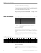
Analog input status values can be read from Global Variables IO_Xx_ST_yy,
where “x” represents the expansion slot number 1…4 and yy represents the status
word number 00…04. Individual bits within a status word can be read by
appending a .zz to the Global Variable name, where "zz" is the bit number 00...15.
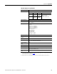
2085-IF8
(1)
Status Data Mapping
Word R/W151413121110987654 3210
Status 0 R PU GF CRC Reserved
Status 1 R Reserved HHA1 LLA1 HA1 LA1 DE1 S1 Reserved HHA0 LLA0 HA0 LA0 DE0 S0
Status 2 R Reserved HHA3 LLA3 HA3 LA3 DE3 S3 Reserved HHA2 LLA2 HA2 LA2 DE2 S2
Status 3 R Reserved HHA5 LLA5 HA5 LA5 DE5 S5 Reserved HHA4 LLA4 HA4 LA4 DE4 S4
Status 4 R Reserved HHA7 LLA7 HA7 LA7 DE7 S7 Reserved HHA6 LLA6 HA6 LA6 DE6 S6
(1) See Bit Field Descriptions table for a detailed definition of each bit.
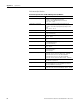
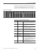
Field Descriptions for 2085-IF4 and 2085-IF8 Input Modules
Field Description
CRC CRC error This bit is set (1) when there is a CRC error on the data
received. It gets cleared when the next good data is
received.
DE# Data Error These bits are set (1) when the enabled input channels are
not getting any reading for the current sampling. The
respective returned Input Data value remains the same as
the previous sample.
GF General Fault This bit is set (1) when any of these faults occur: RAM test
failure, ROM test failure, EEPROM failure, and reserved
bits. All channel fault bits (S#) are set too.
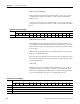
HA# High Alarm
Overrange
These bits are set (1) when the input channel exceeds a
preset high limit defined by the configuration selected (UL#
is set).
HHA# High High Alarm
Overrange
These bits are set (1) when the input channel exceeds a
preset high-high limit defined by the configuration selected
(UL# is set).
LA# Low Alarm
(underrange)
These bits are set (1) when the input channel goes below
the configured low alarm limit.
LLA# Low Low Alarm
(underrange)
These bits are set (1) when the input channel goes below
the configured low-low alarm limit.
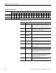
PU Power Up 1. This bit is set after a power on. It is cleared when good
configuration data is accepted by the module.
2. It is set when an unexpected MCU reset occurs in RUN
mode. All channel fault bits (S#) are set too. The module
stays connected with no configuration after the reset. PU
and channel fault bits (S#) are cleared when a good
configuration is accepted.
S# Channel fault These bits are set(1) if the corresponding channels are
open, have data error or under/overrange.