
User guide


60 Rockwell Automation Publication 2080-UM003A-EN-E - March 2013
Appendix B Expansion I/O Data Mapping
2085-OF4 I/O Data Mapping
Analog output data can be written to Global Variables _IO_Xx_AO_yy, where
“x” represents the expansion slot number 1…4 and yy represents the channel
number 00…03.
Control bit states can be written to Global Variable _IO_Xx_CO_00.zz, where
“x” represents the expansion slot number 1…4 and “zz” represents the bit number
00…12.
Channel Alarm/Error Unlatch
UUx and UOx are written during run mode to clear any latched lunder- and
over-range alarms. The alarm is unlatched when the unlatch bit is set (1) and the
alarm condition no longer exists. If the alarm condition persists, then the unlatch
bit has no effect.
CEx are written during run mode to clear any DAC hardware error bits and re-
enable the error-disabled channel x.
You need to keep the unlatch bit set until verification from the appropriate input
channel status word says that the alarm status bit has cleared(0), then you need to
reset(0) the unlatch bit.
Status Data
Analog output status can be read from Global Variables IO_Xx_ST_yy, where “x”
represents the expansion slot number 1…4 and “yy” represents the status word
number 00…06. Individual bits within a status word can be read by appending a
.zz to the Global Variable name, where "zz" is the bit number 00...15.
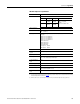
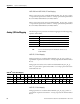
2085-OF4 Control Data Mapping
Word Bit Position
1514131211109876543210
Control 0 Reserved CE3 CE2 CE1 CE0 UU3 UO3 UU2 UO2 UU1 UO1 UU0 UO0
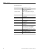
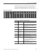
2085-OF4 Status Data Mapping
Word Bit Position
15141312 11109876543210
Status 0 Channel 0 Data Value
Status 1 Channel 1Data Value
Status 2 Channel 2 Data Value
Status 3 Channel 3 Data Value