
Quick Start Instruction Manual

Ultra1500 Digital Drives Quick Start 7
Publication 2092-QS001D-EN-P — July 2005
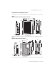
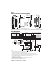
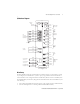
Mating Connectors
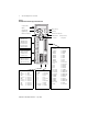
Drive Displays
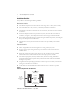
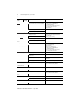
The 7-segment display provides operational information when the drive is functioning, or warning/
error messages when abnormalities are encountered.
Normal operational information consists of six characters that display data in three categories. The
categories consist of a Control Mode (characters 0 and 1), a Row Display (2), and Status (3 to 5).
Figure 6 depicts these categories and defines the information provided. Overtravel displays (see the
table following Figure 6) occur if the drive detects an overtravel condition.
Figure 6
Operational Drive Displays
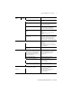
Connector Type Wire Size A-B Connector Kit or
Manufacturer P/N
Input Power Single-row, spring
clamp connectors
with 7.5 mm spacing
2.5 - 0.8 mm
2
(12 - 28 AWG)
8 mm (0.3 in.) of wire
exposed
Wago 231-206/026-000
1
DC Bus and Shunt Power Wago 231-204/026-000
1
Output (Motor) Power Wago 231-203/026-000
1
CN1 - Input/Output 50-pin mini-D 0.2 mm
2
(24 - 30 AWG)
9101-1476
CN2 - Motor Feedback 20-pin mini-D 9101-1477
CN3 - Serial Interface 20-pin mini-D
1 Tool (Wago 231-131) for opening individual cage clamps on above power connectors is supplied.
Overtravel Display Possible Cause Action/Solution
Positive Overtravel
A Positive Overtravel condition is
detected.
Apply motion in a negative direction to back
off limit.
Negative Overtravel
A Negative Overtravel condition is
detected.
Apply motion in a positive direction to back
off limit.
Character: 0 1 2 3 4 5
rdy = Drive is disabled, but ready to be enabled
run = Drive is enabled and motor is under control
Status: Characters 3 through 5
Middle Row = Active if velocity exceeds Up To Speed parameter
Row Display: Character 2
Top Row = Inactive for any Current mode
Active if Velocity Mode. and Velocity Error is within the velocity window
Active if Follower Mode. and Position Error is within following error setting
Bottom Row = Active for hall startup motors once the commutation angle is set
Active for TL motor once the first index pulse occurs
C = Analog Current
d = Dual Current Command
Control Mode: Characters 0 and 1
F = Follower
S = Analog Speed
P = Preset Velocity