Safety Reference Manual Kinetix Safe Torque-off Feature Catalog Numbers 2094-ACxx-Mxx-S, 2094-BCxx-Mxx-S, 2094-AMxx-S, 2094-BMxx-S, 2099-BMxx-S Original Instructions
Important User Information Solid-state equipment has operational characteristics differing from those of electromechanical equipment. Safety Guidelines for the Application, Installation and Maintenance of Solid State Controls (publication SGI-1.1 available from your local Rockwell Automation® sales office or online at http://www.rockwellautomation.com/literature/) describes some important differences between solid-state equipment and hard-wired electromechanical devices.
Summary of Changes This manual contains new and updated information. New and Updated Information This revision includes changes for the Kinetix 6000 series C servo drives. Topic Page Updated references to safe-off (SO) as safe torque-off (STO), per EN 61800-5-2. Replaced references to EN 954-1 with EN ISO 13849-1. Throughout this manual Updated safe torque-off descriptive text, including certification, description of operation, and PFD/PFH definitions and data.
Summary of Changes Notes: 4 Rockwell Automation Publication GMC-RM002F-EN-P - June 2013
Table of Contents Preface About This Publication. . . . . . . . . . . . . . . . . . . . . . . . . . . . . . . . . . . . . . . . . . . . . 7 Audience . . . . . . . . . . . . . . . . . . . . . . . . . . . . . . . . . . . . . . . . . . . . . . . . . . . . . . . . . . 7 Conventions Used in This Manual . . . . . . . . . . . . . . . . . . . . . . . . . . . . . . . . . . 7 Terminology. . . . . . . . . . . . . . . . . . . . . . . . . . . . . . . . . . . . . . . . . . . . . . . . . . . . . . .
Table of Contents Appendix B Kinetix Safe Torque-off Wiring Diagrams Kinetix Safe Torque-off/Safety Relay Configurations. . . . . . . . . . . . . . . . 32 Kinetix Safe Torque-off/GuardLogix Configurations. . . . . . . . . . . . . . . . 35 Kinetix Safe Torque-off/GuardPLC Configurations . . . . . . . . . . . . . . . . 39 Appendix C EC Certifications EC Type - Examination Certificate . . . . . . . . . . . . . . . . . . . . . . . . . . . . . . . . 43 EC Declaration of Conformity . . . . . . . . . . . . . .
Preface About This Publication This manual provides detailed installation instructions for wiring and troubleshooting your Kinetix 6000 and Kinetix 7000 safe torque-off drives. Included are interconnect diagrams with Allen-Bradley safety relays, GuardLogix controllers, and GuardPLC controllers.
Preface These documents contain additional information concerning related Rockwell Automation products. Additional Resources Resource Description Kinetix 6000 Multi-axis Servo Drive User Manual, publication 2094-UM001 Detailed mounting, wiring, setup with RSLogix 5000 software, applying power, and troubleshooting information, with appendices to support firmware upgrades, common bus applications, and Bulletin 2090 resistive brake module (RBM) applications.
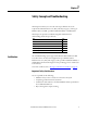
Chapter 1 Safety Concept and Troubleshooting This chapter introduces you to how the safe torque-off feature meets the requirements of Performance Level e (PLe) and safety category 3 (CAT 3) per EN ISO 13849-1 and SIL 3 per IEC 61508, EN 61800-5-2 and EN 62061. This chapter also provides a troubleshooting table and flowchart for understanding the Safe Torque-off mode.
Chapter 1 Safety Concept and Troubleshooting Category 3 Requirements According to EN ISO 13849-1 Safety-related parts are designed with these attributes: • A single fault in any of these parts does not lead to the loss of the safety function. • A single fault is detected whenever reasonably practicable. • Accumulation of undetected faults can lead to the loss of the safety function, which results in failure to remove motion-producing power from the motor.
Safety Concept and Troubleshooting Chapter 1 Low Voltage Directive These units are tested to meet Council Directive 2006/95/EC Low Voltage Directive. The EN 60204-1 Safety of Machinery-Electrical Equipment of Machines, Part 1-Specification for General Requirements standard applies in whole or in part. Additionally, the standard EN 61800-5-1 Electronic Equipment for use in Power Installations apply in whole or in part.
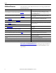
Chapter 1 Safety Concept and Troubleshooting PFD and PFH Data These PFD and PFH calculations are based on the equations from IEC 61508 and show worst-case values. Table 1 provides test data and demonstrates the worst-case effect of various configuration changes on the data. Table 1 - PFD and PFH Proof Test Interval Attribute Kinetix 6000 Drives Kinetix 7000 Drives PFH 0.26 (e-9) 0.38 (e-9) PFD 0.045 (e-3) 0.
Safety Concept and Troubleshooting Chapter 1 Understanding the Safe Torque-off Condition vs Drive Fault When both inputs de-energize within 100 ms, a fault does not occur (E49 is not displayed), however, a safe torque-off state is entered within the 25 ms response time. The safe torque-off condition occurs through normal drive operation. A mismatch occurs when one input is de-energized while the other input is energized after 100 ms.
Chapter 1 Safety Concept and Troubleshooting Figure 3 - Advanced Safe Torque-off Troubleshooting Flowchart Start Bulletin 2099 or Bulletin 2094 with safe torque-off (-S) drive? Yes RSLogix 5000 software v15 or v16? v15 1 No 1 Safe Torque-off condition exists through normal operation. Both inputs de-energized within 100 ms of each other. Resolve safe torque-off condition. Complete MSF 1 instruction.
Chapter 2 Safe Torque-off Connector Data This chapter provides safe torque-off (STO) connector, header, and interface cable information for the Kinetix 6000 and Kinetix 7000 safe torque-off drives.
Chapter 2 Safe Torque-off Connector Data Figure 4 - 9-pin Safe Torque-off (STO) Connector - Kinetix 6000 Drive U 4 5 6 L3 MBRK - L2 MBRK + COM L1 PWR 1 2 CONT EN- DBRK - CONT EN+ DBRK + RX TX DPI W V U MBRK MBRK + COM PWR DBRK DBRK + BAUD RATE Integrated Axis Module (IAM), Top View (2094-BC01-MP5-S is shown) RX 1 2 3 4 5 6 7 8 9 Safe Torque-off (STO) Connector Kinetix 7000 Drive Module, Top View (2099-BM06-S is shown) Rockwell Automation Publication GMC-RM002F-EN-P - June 2013 TX
Safe Torque-off Connector Data Safe Torque-off Header Configurations Chapter 2 The safe torque-off function can be implemented in a single-drive or extended in up to eight drives in a multiple safety-drive configuration. The connector can also be jumpered to effectively remove the safe torque-off function. In this example, the Kinetix 6000 axis module is shown with the motion-allowed jumper installed in the wiring plug header.
Chapter 2 Safe Torque-off Connector Data In this example, the Kinetix 6000 axis module is shown with a first-drive wiring header (catalog number 2090-XNSM-W). Kinetix 6000 and Kinetix 7000 firstdrive modules use this header in multiple safe torque-off drive configurations for wiring to a safety control circuit and extending the safe torque-off circuitry to another drive. Figure 8 - First-drive Wiring Header (2090-XNSM-W) Cable connector to second drive in safety circuit.
Safe Torque-off Connector Data Chapter 2 In this example, the Kinetix 6000 axis module is shown with a drive-to-drive middle header (catalog number 2090-XNSM-M). Kinetix 6000 and Kinetix 7000 drive modules, in safe torque-off drive configurations of three or more, use this header for making the safe torque-off connections between drives. Figure 10 - Middle Drive Header (2090-XNSM-M) Cable connectors to the next and previous drive in safety circuit.
Chapter 2 Safe Torque-off Connector Data An assortment of headers, when wired and plugged into the safe torque-off (STO) connector, make implementation possible, as described in this table. Safe Torque-off Accessories Table 4 - Safe Torque-off Headers Description Cat. No. Safe Torque-off wiring header for the first drive in multiple safety drive configurations (optional).
Chapter 3 Wiring Your Kinetix Safe Torque-off Drive This chapter provides guidelines for wiring your Kinetix 6000 and Kinetix 7000 safe torque-off drive connections. Wire the Safe Torque-off Circuit Topic Page Wire the Safe Torque-off Circuit 21 Safe Torque-off Wiring Requirements 22 Safe Torque-off Feature 23 This section provides guidelines for wiring your Kinetix 6000 and Kinetix 7000 safe torque-off drive connections.
Chapter 3 Wiring Your Kinetix Safe Torque-off Drive These are the safe torque-off (STO) wiring requirements. Wire should be copper with 75 °C (167 °F) minimum rating. Safe Torque-off Wiring Requirements IMPORTANT The National Electrical Code and local electrical codes take precedence over the values and methods provided.
Wiring Your Kinetix Safe Torque-off Drive Safe Torque-off Feature Chapter 3 The safe torque-off circuit, when used with suitable safety components, provides protection according to EN ISO 13849-1 (PLe), Cat3 or according to EN 62061 (SIL3). The safe torque-off option is just one safety control system. All components in the system must be chosen and applied correctly to achieve the desired level of operator safeguarding.
Chapter 3 Wiring Your Kinetix Safe Torque-off Drive Safe Torque-off Connection Examples Typical safe torque-off connections for the Kinetix 6000 and Kinetix 7000 drives are shown in the figures below. In this example, a single Kinetix 6000 safe torque-off drive is shown using the wiring plug header. The second and third drives do not use the safe torque-off feature, so the motion-allowed jumpers remain installed.
Wiring Your Kinetix Safe Torque-off Drive Chapter 3 In this example, system 1 contains two (single-wide) Kinetix 6000 drives using the safe torque-off feature wired with two (double-wide) Kinetix 6000 drives in system 2. The wiring headers with motion-allowed jumpers have been replaced as shown. The third axis in system 1 does not use the safe torque-off feature, so the wiring header and motion-allowed jumper remain installed.
Chapter 3 Wiring Your Kinetix Safe Torque-off Drive In this example, the Kinetix 6000 power rail contains three (single-wide) drives using the safe torque-off feature and wired with one Kinetix 7000 drive. The wiring headers and motion-allowed jumpers have been replaced as shown.
Wiring Your Kinetix Safe Torque-off Drive Chapter 3 Safe Torque-off Wiring Examples for SIL 3 Applications The following illustrations show typical wiring diagrams for the Kinetix 6000 and Kinetix 7000 safe torque-off drives: • Typical single drive (stop category 0) configuration • Typical single drive (stop category 1) configuration ATTENTION: Category 1 (controlled stop) must be used and zero speed verified, prior to engaging the motor holding (parking) brake.
Chapter 3 Wiring Your Kinetix Safe Torque-off Drive Figure 17 - Single Drive (Stop Category 1) with Safety Relay Configuration Kinetix 6000 IAM/AM Module or Kinetix 7000 Drive Safety Relay Rated for SIL 3 per IEC 61508 1 Estop Out 22 24V Com 2 24V + Estop Out 12 Estop IN 11 3 Safe Torque-off Demand 4 5 Estop IN 21 6 7 Reset Out 12 Reset PB Reset IN 21 N.C. 8 N.C.
Appendix A Specifications This chapter provides safe torque-off feature specifications for your Kinetix 6000 and Kinetix 7000 drives. Safe Torque-off Response Time Specifications Topic Page Safe Torque-off Response Time Specifications 29 Safe Torque-off Signal Specifications 29 The system reaction time is the amount of time from a safety-related event as input to the system until the system is in the safe state.
Appendix A Specifications Table 9 - Relay Contact Specifications for the FDBK Signals Attribute Value Contact Resistance (1 A, 24V DC) ≤ 100 mΩ Contact Resistance (10 mA, 5V DC) ≤ 20 Ω Contact Load (min) 10 mA, 5V DC Rated Current 5A Rated Voltage 240V ac Breaking Capacity, ac (max) for resistive loads 1250VA Kinetix 6000 (series C) Servo Drives Table 10 - Safe Torque-off Signal Specifications Attribute Value Input current < 10 mA Input ON voltage range 18…26.
Appendix B Kinetix Safe Torque-off Wiring Diagrams This appendix provides typical wiring diagrams for the Kinetix 6000 and Kinetix 7000 safe torque-off drives with other Allen-Bradley safety products.
Appendix B Kinetix Safe Torque-off Wiring Diagrams In the diagrams beginning below, the Kinetix 6000 and Kinetix 7000 drive safe torque-off connector is shown wired to an Allen-Bradley safety relay.
Kinetix Safe Torque-off Wiring Diagrams Appendix B Figure 20 - Multi-axis Relay Configuration (Stop Category 0) External +24V DC Reset Safe Torque-off Demand Kinetix 6000 IAM/AM Module or Kinetix 7000 Drive A1 S11 S52 S12 13 23 33 1 41 2 3 Allen-Bradley Monitoring Safety Relay MSR127RP (440R-N23135) 4 5 6 S21 S22 S34 A2 14 24 34 7 42 FDBK2+ FDBK2FDBK1+ FDBK1SAFETY ENABLE2+ SAFETY ENABLE - Safe Torque-off (STO) Connector with First-drive Wiring Header (2090-XNSM-W) SAFETY ENABLE1+
Appendix B Kinetix Safe Torque-off Wiring Diagrams Figure 21 - Multi-axis Relay Configuration (Stop Category 1) External +24V DC Safe Torque-off Demand Kinetix 6000 IAM/AM Module or Kinetix 7000 Drive Reset 1 2 A1 S52 S11 S12 S21 S22 S33 S34 13 23 37 47 55 3 4 5 Allen-Bradley Monitoring Safety Relay MSR138.
IMPORTANT TM 24V COM V- CAN_L Drain CAN_H V+ +24V DC Rockwell Automation Publication GMC-RM002F-EN-P - June 2013 0 G0 T0 V0 T1 1 T0 2 T1 3 T0 4 T1 5 T3 7 24V COM T2 6 Allen-Bradley GuardLogix Safety I/O Module 1791DS-IB8X0B8 +24V DC G1 V1 G1 V1 G1 0 G1 1 G1 2 G1 3 G1 4 G1 5 G1 6 G1 7 N.C. 9 N.C.
IMPORTANT Rockwell Automation Publication GMC-RM002F-EN-P - June 2013 Safe Torque-off Demand 24V COM V- CAN_L Drain CAN_H V+ +24V DC G0 V0 0 G0 T0 V0 ControlLogix Chassis T1 1 T0 2 T1 3 T0 4 T1 5 T2 6 24V COM T3 7 Allen-Bradley GuardLogix Safety I/O Module 1791DS-IB8X0B8 +24V DC G1 V1 G1 V1 G1 0 G1 1 G1 2 G1 3 G1 4 G1 5 G1 6 G1 7 Proper logic and commissioning of the safety controller must be configured.
IMPORTANT 24V COM V- CAN_L Drain CAN_H V+ +24V DC Rockwell Automation Publication GMC-RM002F-EN-P - June 2013 0 G0 T0 V0 T1 1 T0 2 T1 3 T0 4 T1 5 T2 6 24V COM T3 7 Allen-Bradley GuardLogix Safety I/O Module 1791DS-IB8X0B8 +24V DC G1 V1 G1 0 G1 1 G1 2 G1 3 G1 4 G1 5 Safe Torque-off (STO) Connector with Terminating Header (2090-XNSM-T) Kinetix 6000 IAM/AM Module or Kinetix 7000 Drive G1 V1 G1 6 G1 7 Safe Torque-off Interface Cable 1202-Cxx SAFETY ENABLE1+ SAFETY ENABLE -
IMPORTANT 24V COM V- CAN_L Drain CAN_H V+ +24V DC Rockwell Automation Publication GMC-RM002F-EN-P - June 2013 0 G0 T0 V0 T1 1 T0 2 T1 3 T0 4 T1 5 T2 6 24V COM T3 7 Allen-Bradley GuardLogix Safety I/O Module 1791DS-IB8X0B8 +24V DC G1 V1 G1 V1 Proper logic and commissioning of the safety controller must be configured.
24V COM DI DI DI 1753-L28BBM 20 DC Inputs 8 DC Outputs Guard PLC 1600 13 14 15 16 17 18 19 20 21 22 23 24 25 26 27 28 29 30 31 32 33 34 35 36 37 38 39 40 41 42 LS+ 1 2 3 4 L- LS+ 5 6 7 8 L- LS+ 9 10 11 12 L- LS+13 14 15 16 L- LS+17 18 19 20 L- DI DO DO DI L- 5 6 7 8 L- L- 1 2 3 4 L- Allen Bradley 7 8 9 10 11 12 1 2 3 4 5 6 8 9 N.C. N.C.
24V COM Rockwell Automation Publication GMC-RM002F-EN-P - June 2013 DO DO DI DI 1753-L28BBM 20 DC Inputs 8 DC Outputs Guard PLC 1600 13 14 15 16 17 18 19 20 21 22 23 24 25 26 27 28 29 30 31 32 33 34 35 36 37 38 39 40 41 42 LS+ 1 2 3 4 L- LS+ 5 6 7 8 L- LS+ 9 10 11 12 L- LS+13 14 15 16 L- LS+17 18 19 20 L- DI DI L- 5 6 7 8 L- L- 1 2 3 4 L- DI 7 8 9 10 11 12 1 2 3 4 5 6 Allen Bradley Safe Torque-off Demand L- L- L+ L+ +24V DC +24V DC Power Supply N.C. N.C.
24V COM Rockwell Automation Publication GMC-RM002F-EN-P - June 2013 DI DI DI 1753-L28BBM 20 DC Inputs 8 DC Outputs Guard PLC 1600 Safe Torque-off (STO) Connector with Terminating Header (2090-XNSM-T) Kinetix 6000 IAM/AM Module or Kinetix 7000 Drive 13 14 15 16 17 18 19 20 21 22 23 24 25 26 27 28 29 30 31 32 33 34 35 36 37 38 39 40 41 42 LS+ 1 2 3 4 L- LS+ 5 6 7 8 L- LS+ 9 10 11 12 L- LS+13 14 15 16 L- LS+17 18 19 20 L- DI DO DO DI L- 5 6 7 8 L- 7 8 9 10 11 12 L- 1 2 3 4 L- 1 2 3 4 5 6 Alle
24V COM Rockwell Automation Publication GMC-RM002F-EN-P - June 2013 DO DO DI DI DI 1753-L28BBM 20 DC Inputs 8 DC Outputs Guard PLC 1600 24V_COM Hardware Enable Input I/O (IOD) Connector Safe Torque-off (STO) Connector with Terminating Header (2090-XNSM-T) Kinetix 6000 IAM/AM Module or Kinetix 7000 Drive 2 3 3 Safe Torque-off Interface Cable 1202-Cxx 3 2 7 6 5 4 3 2 1 2 Safe Torque-off Interface Cable 1202-Cxx 13 14 15 16 17 18 19 20 21 22 23 24 25 26 27 28 29 30 31 32 33 34 35
Appendix C EC Certifications This appendix provides Kinetix 6000 and Kinetix 7000 servo drive certification information. EC Type - Examination Certificate Topic Page EC Type - Examination Certificate 43 EC Declaration of Conformity 45 For complete product certifications currently available from Rockwell Automation, go to http://www.rockwellautomation.com/products/certification.
Appendix C EC Certifications Figure 31 - Kinetix 7000 Servo Drives Certificate 44 Rockwell Automation Publication GMC-RM002F-EN-P - June 2013
EC Certifications Appendix C For complete declarations of conformity (DoC) currently available from Rockwell Automation, go to http://www.rockwellautomation.com/products/certification. EC Declaration of Conformity Figure 32 - Kinetix 6000 Servo Drives EC DoC EC Declaration of Conformity The undersigned, representing the manufacturer Rockwell Automation, Inc. 6400 W. Enterprise Drive Mequon, WI 53092 U.S.A. and the authorized representative established within the Community Rockwell Automation B.V.
Appendix C EC Certifications Catalogue number Series 3 Description Bulletin 2094 Servo Drives1,6,11,12,13 2094-BC01-MP5 460 Volt Integrated Axis Module 6 kW Inverter 2.8 Amp 2094-BC01-M01 460 Volt Integrated Axis Module 6 kW Inverter 6.1 Amp 2094-BC02-M02 460 Volt Integrated Axis Module 15 kW Inverter 10.3 Amp 2094-BC04-M03 460 Volt Integrated Axis Module 28 kW Inverter 21.2 Amp 2094-BC07-M05 460 Volt Integrated Axis Module 45 kW Inverter 34.
EC Certifications Appendix C Figure 33 - Kinetix 7000 Servo Drives EC DoC EC Declaration of Conformity The undersigned, representing the manufacturer Rockwell Automation, Inc. 6400 W.
Appendix C EC Certifications Catalogue number 2 Series 1 Description Note: The following motor/drive combinations are permitted for the purposes of this declaration.
Index A about this publication 7 C cables drive-to-drive 20, 25, 26 catalog, safety products 31 category 3 requirements 10 stop category definitions 10 CE comply with CE 10 conformity 10 meet requirements 11 certification EC Declaration of Conformity Kinetix 6000 45 Kinetix 7000 47 EC Type - Examination Certificate Kinetix 6000 43 Kinetix 7000 44 TÜV Rheinland 9 user responsibilities 9 connector location 16 pinout 15 sets 20 conventions 7 D H headers 20 first-drive wiring 18 last-drive 19 middle-drive 19
Index STO connector 23 wiring 22 T terminology 7 training 7 troubleshooting 12 error code E49 12 flowchart 14 safe torque-off condition 13 safe torque-off drive fault 13 W wiring GuardLogix examples 35 GuardPLC examples 39 plug header 17 requirements 22 safe torque-off bypass 23 safety relay examples 32 STO connector 22 stop cat. 0 example 27 stop cat.
Rockwell Automation Support Rockwell Automation provides technical information on the Web to assist you in using its products. At http://www.rockwellautomation.com/support, you can find technical manuals, technical and application notes, sample code and links to software service packs, and a MySupport feature that you can customize to make the best use of these tools. You can also visit our Knowledgebase at http://www.rockwellautomation.