
Reference Manual

Rockwell Automation Publication GMC-RM002F-EN-P - June 2013 27
Wiring Your Kinetix Safe Torque-off Drive Chapter 3
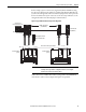
Safe Torque-off Wiring Examples for SIL 3 Applications
The following illustrations show typical wiring diagrams for the Kinetix 6000
and Kinetix 7000 safe torque-off drives:
• Typical single drive (stop category 0) configuration
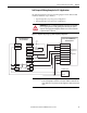
• Typical single drive (stop category 1) configuration
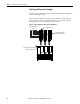
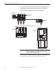
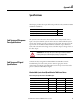
Figure 16 - Single Drive (Stop Category 0) with Safety Relay Configuration
ATTENTION: Category 1 (controlled stop) must be used and zero speed verified,
prior to engaging the motor holding (parking) brake. Disabling the output by
any means and engaging the holding brake with the motor in motion will result
in premature failure of the brake.
1
2
3
4
5
6
7
8
9
FDBK2+
FDBK2-
FDBK1+
FDBK1-
SAFETY ENABLE2+
SAFETY ENABLE -
SAFETY ENABLE1+
24V +
24V_COM
24V Com
Estop Out 12
Estop Out 22
Estop IN 11
Estop IN 21
Reset Out 12
Reset IN 21
N.C.
N.C.
24V +
Safe Torque-off
(STO) Connector
with
Wiring Header
Safe Torque-off
Demand
Reset PB
Safety Relay Rated for
SIL 3 per IEC 61508
Kinetix 6000 IAM/AM Module or
Kinetix 7000 Drive
24V+
24V Power Supply
24V Com
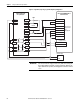
IMPORTANT
Pins STO-8 (internal 24V+ supply) and STO-9 (24V_COM) are used only by the
motion-allowed jumper to defeat the safe torque-off function. When the safe
torque-off function is in operation, the 24V supply must come from an external
source.