
Reference Manual

Rockwell Automation Publication GMC-RM002F-EN-P - June 2013 35
Kinetix Safe Torque-off Wiring Diagrams Appendix B
Kinetix Safe Torque-off/
GuardLogix Configurations
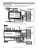
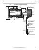
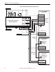
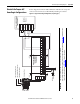
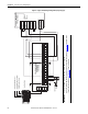
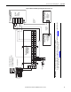
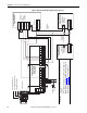
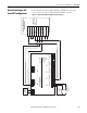
In these diagrams, the Kinetix 6000 and Kinetix 7000 drive safe torque-off
connector is shown wired to an Allen-Bradley GuardLogix controller.
Figure 22 - Single-axis GuardLogix Configuration (Stop Category 0)
V0 V0 0 1 2 3 4 5 6 7
G0 G0 T0 T1 T0 T1 T0 T1 T2 T3
V1 V1 0 1 2 3 4 5 6 7
G1 G1 G1 G1 G1 G1 G1 G1 G1 G1
V+
CAN_H
Drain
CAN_L
V-
1
2
3
4
5
6
7
8
9
FDBK2+
FDBK2-
FDBK1+
FDBK1-
SAFETY ENABLE2+
SAFETY ENABLE -
SAFETY ENABLE1+
24V +
24V_COM
N.C.
N.C.
DeviceNet
TM
Kinetix 6000 IAM/AM Module
or Kinetix 7000 Drive
Allen-Bradley GuardLogix
Safety I/O Module
1791DS-IB8X0B8
Safe Torque-off
(STO) Connector
with
Wiring Header)
24V COM
Safe Torque-off
Demand
+24V DC
24V COM
+24V DC
1756-L61S GuardLogix Processor
1756-LSP GuardLogix Safety Partner
1756-DNB DeviceNet Module
ControlLogix Chassis
IMPORTANT
Proper logic and commissioning of the safety controller must be configured.
Refer to the DeviceNet Modules in Logix5000 Control Systems User Manual, publication DNET-UM004
, and the DeviceNet
Safety User Manual, publication 1791DS-UM001
, for more information.