
Owner manual

Publication PFLEX-IN028A-EN-P - February 2012
Installation Instructions
Balancing Resistor Kit for 600/690V Frame 13 PowerFlex
700AFE and 600/690V Frame 13 and 14 PowerFlex 700H/700S
AC Drives
Who Should Use These
Instructions
These instructions are intended only for use by qualified Rockwell Automation
Field Service personnel. Contact Rockwell Automation Customer Service to
arrange for the installation of the kit(s).
Topic Page
Who Should Use These Instructions
1
Additional Resources 2
What the Kit Contains 2
Number of Kits Required 2
Arranging for Kit Installation 2
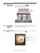
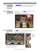
Step 1: Remove the Power Structure Covers 3
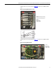
Step 2: Remove the ASIC-to-Control Pan Cable Set 3
Step 3: Remove ASIC Board Cover 3
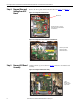
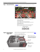
Step 4: Remove Wires and Cabling from ASIC Board 4
Step 5: Remove ASIC Board Assembly 4
Step 6: Remove Voltage Feedback Board Sheetmetal Cover (if applicable) 5
Step 7: Unplug Main Fan and Fan Inverter Supply Connectors 5
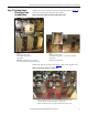
Step 8: Remove Supply Wires from Fuse Bases 5
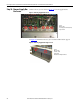
Step 9: Remove DC Bus Bars 6
Step 10: Remove Voltage Supply Cables 6
Step 11: Remove Power Phase Units from Assembly Base 7
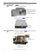
Step 12: Remove Phase Units from Mounting Base 8
Step 13: Remove EMC Shield Unit 8
Step 14: Remove Supply Bus Bar Screws 10
Step 15: Access Balancing Resistor Assembly 11
Step 16: Install New Spare Parts Kit Components 11
Step 17: Re-Assemble the Product 12
Step 18: Attach New Label 12
IMPORTANT
The customer should not attempt to use these instructions to
install the kit(s), as this will void the product warranty.