DC SCR Precharge Module User Manual
Important User Information Solid state equipment has operational characteristics differing from those of electromechanical equipment. Safety Guidelines for the Application, Installation and Maintenance of Solid State Controls (Publication SGI-1.1 available from your local Rockwell Automation sales office or online at http:// www.rockwellautomation.com/literature) describes some important differences between solid state equipment and hard-wired electromechanical devices.
Summary of Changes This is the first release of this publication.
soc-ii Summary of Changes
Table of Contents Preface Overview Who Should Use this Manual? . . . . . . . . . . . . . . . . . . . . . . . . . . . . . . . . . . . . . . . . . . . . . Installation Requirement . . . . . . . . . . . . . . . . . . . . . . . . . . . . . . . . . . . . . . . . . . . . . . . . . . Reference Materials . . . . . . . . . . . . . . . . . . . . . . . . . . . . . . . . . . . . . . . . . . . . . . . . . . . . . Manual Conventions . . . . . . . . . . . . . . . . . . . . . . . . . . . . . . . . . . . . . . . . . . . .
ii Table of Contents
Preface Overview The purpose of this manual is to provide you with the basic information needed to install, start-up, and troubleshoot the DC SCR Precharge Module. For information on ... Who Should Use this Manual? Installation Requirement Reference Materials Manual Conventions General Precautions Part Number Explanation Description and Block Diagram See page ...
P-2 Overview Manual Conventions The following words are used throughout the manual to describe an action: Word Can Cannot May Must Shall Should Should Not General Precautions ! ! ! ! ! ! Meaning Possible, able to do something Not possible, not able to do something Permitted, allowed Unavoidable, you must do this Required and necessary Recommended Not recommended ATTENTION: The DC SCR Precharge Module contains ESD (Electrostatic Discharge) sensitive parts and assemblies.
Overview Part Number Explanation P-3 The available ratings for the DC SCR Precharge Module are shown below: Module Rating (DC Amps) 500A 750A 1000A 1600A DC SCR Precharge Module Part Number with Aluminum Heatsink with Nickel-Plated Heatsink 370696 370724 370711 370729 370715 370733 370707 370737 Important: These DC SCR Precharge Modules are available for 380-480 VAC drive applications only.
Overview Description and Block Diagram The DC SCR Precharge Module has been designed to limit the current draw by the drive’s capacitor bank during precharge operation. This is accomplished using precharge resistors. When the operational DC bus voltage has been achieved, the continuous current is then conducted through the SCR in the SCR Power Module. In addition, a diode integrated into the SCR Power Module provides regenerative capability. Figure P.
Chapter 1 Installation/Wiring This chapter provides information on installing and wiring the DC SCR Precharge Module. For information on ... Minimum Mounting Clearances Ambient Operating Temperature AC Supply Source Considerations General Grounding Requirements Fuses Minimum Capacitance Maximum Loading Power Wiring Control Wiring and Terminals Control Wiring Requirements Drive Run Interlock Typical Power and Control Wiring Examples See page ...
1-2 Installation/Wiring Minimum Mounting Clearances The air inlet and outlet areas for each DC SCR Precharge Module must be a minimum of 200 square centimeters (31 square inches). The Length-to-Width Ratio must not exceed 4:1. Figure 1.1 Minimum Mounting Clearance for 500A and 750A DC SCR Precharge Modules Air Outlet Air Flow GND G AK HK K Fan 120 mm (4.7 in.) 120 mm (4.7 in.
Installation/Wiring AC Supply Source Considerations 1-3 The DC SCR Precharge Modules are suitable for use on a circuit capable of delivering a short circuit rating up to a maximum of 65,000 rms symmetrical amperes. If a Residual Current Detector (RCD) is used as a system ground fault monitor, only Type B (adjustable) devices should be used to avoid nuisance tripping.
1-4 Installation/Wiring (girder, joist), a floor ground rod, bus bar or building ground grid. Grounding points must comply with national and local industrial safety regulations and/or electrical codes. Fuses The DC SCR Precharge Module is designed for internal application inside the drive(s) enclosure. The customer may install the external DC bus fuses if the fuse protection does not exist inside the drive.
Installation/Wiring Power Wiring ! 1-5 ATTENTION: National Codes and standards (NEC, VDE, BSI, etc.) and local codes outline provisions for safely installing electrical equipment. Installation must comply with specifications regarding wire types, conductor sizes, and disconnect devices. Failure to do so may result in personal injury and/or equipment damage.
Installation/Wiring Power Connection for 500A and 750A DC SCR Precharge Modules Figure 1.4 shows typical locations of bus bars and terminals on 500A and 750A DC SCR Precharge Modules for customer wiring. Figure 1.4 Bus Bar and Terminal Locations for Wiring 500A and 750A Modules ➌ GND ➍ K HK G AK ➍ DANGER CAN CAUSE SHOCK BURNS, OR DEATH DATA NAMEPLATE ➊ SURFACES MAY BE HOT DANGER REMOTE SOURCE A 1-6 +DCin +DCout ➋ Table 1.
Installation/Wiring 1-7 Power Connection for 1000A and 1600A DC SCR Precharge Modules Figure 1.5 shows typical locations of bus bars and terminals on 1000A and 1600A DC SCR Precharge Modules for customer wiring. Figure 1.5 Bus Bar and Terminal Locations for Wiring 1000A and 1600A Modules ➌ ➍ ➍ G +DCin HK GND DANGER CAN CAUSE SHOCK BURNS, OR DEATH SURFACES MAY BE HOT ➊ DANGER REMOTE SOURCE ➋ +DCout Table 1.C Power Connection Specifications for 1000A and 1600A Modules Amps Bus Bars (1) Holes 76.
1-8 Installation/Wiring Control Wiring and Terminals Terminal blocks TB1A and TB2A contain connection points for control wiring of the DC SCR Precharge Module. Table 1.D Control Terminal Specifications for TB1A and TB2A Name Control Terminal Blocks (1) Wire Size Range (1) Maximum Minimum 2.5 sq. mm 0.25 sq. mm (14 AWG) (22 AWG) Torque 0.8 Nm (7 lb.-in.) Maximum/minimum sizes that the terminals will accept – these are not recommendations. Figure 1.
Installation/Wiring 1-9 Figure 1.7 Control Terminal Block TB1A (located on precharge control board) CR 8 7 6 5 4 3 2 1 3 2 1 14 13 12 11 10 9 TB1A Terminal No. 1 2 3 Control Wiring Requirements Wiring Description Notes — — — +DCin (1) (2) +DC (positive) Bus Input Power -DC (negative) Bus Power +DC (positive) Bus Output Power -DC (1) (3) +DCout (1) (2) (1) Refer to Appendix A for contact rating. (2) Terminal TB1A-1 is supplied jumpered to +DCin, and TB1A-2 is supplied jumpered to +DCout.
1-10 Installation/Wiring Typical Power and Control Wiring Examples Figure 1.8 Typical Power and Control Wiring of DC SCR Precharge Module for PowerFlex 700H/700S Drive Applications EA1 I/O Terminal Block 11 Digital IN1 (Stop) (Parameter 361 = 4) 480 VAC 3-Phase Input Power 12 Digital IN2 (Start) (Parameter 362 = 5) 13 Digital IN3 Digital IN4 (Speed Sel.
Installation/Wiring 1-11 Figure 1.
1-12 Notes: Installation/Wiring
Chapter 2 Start-Up / Troubleshooting This chapter describes how to start up the DC SCR Precharge Module and provides basic troubleshooting information. For information on ... Start-Up Precharge Control Relay CR LED Indicator Troubleshooting ! ! ! See page ... 2-2 2-3 2-4 ATTENTION: To avoid an electric shock hazard, verify that the voltage on the bus capacitors has discharged before removing the connection.
2-2 Start-Up / Troubleshooting Start-Up Before Applying Power to the DC SCR Precharge Module ❏ 1. Verify that a minimum of one drive is connected to the DC bus. See Minimum Capacitance on page 1-4 for details. ❏ 2. Verify that all inputs are connected to the correct terminals and are properly torqued. ❏ 3. Using an ohmmeter or other continuity testing device, verify that shorts do not exist between the “+DCin,” “+DCout,” and “-DC” terminals. ❏ 4.
Start-Up / Troubleshooting 2-3 Applying AC Power to the Drive with the DC SCR Precharge Module ❏ 10.Apply AC power and control voltage (115 VAC) to the DC SCR Precharge Module. The green LED on the Precharge Control Relay CR should be on if the drive control logic completes precharge and the SCR control starts gating the SCR power module. ❏ 11.If the green LED on the Precharge Relay CR is not on at this point, disconnect incoming power and refer to Table 2.B for troubleshooting.
2-4 Start-Up / Troubleshooting Troubleshooting Table 2.B provides information for troubleshooting the DC SCR Precharge Module. Table 2.B Possible Symptoms and Corrective Actions Symptom DC output voltage loss Cause/Indication DC bus: • Short circuit or • Low line Corrective Action 1. Check 3-phase AC incoming power for undervoltage or phase loss. 2. Check the protection Precharge fuse F1. 3. After precharge is completed, verify that the values of the “+DCin” and “+DCout” voltages are within 1 volt.
Appendix A Specifications and Dimensions For information on ... Specifications Dimensions See page ...
A-2 Specifications and Dimensions Dimensions Figure A.1 shows the recommended dimensions for panel mounting the DC SCR Precharge Module. Figure A.1 DC SCR Precharge Module Panel Mounting Dimensions Front View A Precharge Module Dimensions DC Rating A B 500A 285 mm 325 mm (11.22 in.) (12.8 in.) 750A 285 mm 325 mm (11.22 in.) (12.8 in.) 1000A 285 mm 325 mm (11.22 in.) (12.8 in.) 1600A 285 mm 325 mm (11.22 in.) (12.8 in.) B Ø 10 mm Ø 0.43 in. 4 Holes Weight 17 kg (37 lbs.) 17 kg (37 lbs.
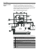
Specifications and Dimensions Figure A.2 Overall Dimensions for 500A and 750A Precharge Modules K HK G AK GND DANGER B SURFACES MAY BE HOT DANGER REMOTE SOURCE A DATA NAMEPLATE CAN CAUSE SHOCK BURNS, OR DEATH +DCin +DCout C A D Front View Side View Precharge Module Dimensions DC Rating A B 500A 369 mm 394 mm (14.5 in.) (15.5 in.) 750A 369 mm 394 mm (14.5 in.) (15.5 in.) C 275 mm (10.8 in.) 275 mm (10.8 in.) D 302 mm (11.9 in.) 302 mm (11.9 in.
A-4 Specifications and Dimensions Figure A.3 Overall Dimensions for 1000A and 1600A Precharge Modules G +DCin HK GND D B DANGER CAN CAUSE SHOCK BURNS, OR DEATH SURFACES MAY BE HOT DANGER REMOTE SOURCE +DCout A C Front View Side View Precharge Module Dimensions DC Rating A B 1000A 428 mm 465 mm (16.8 in.) (18.3 in.) 1600A 428 mm 465 mm (16.8 in.) (18.3 in.) C 317 mm (12.5 in.) 317 mm (12.5 in.) D 810 mm (31.9 in.) 810 mm (31.9 in.
Index A AC supply source considerations, 1-3 J jumper W1, W2, and W3 locations, 2-3 ambient operating temperature, 1-2 L B LED, precharge Control Relay CR, 2-3 block diagram/description, P-4 bus bar and terminal locations 1000A and 1600A modules, 1-7 500A and 750A modules, 1-6 bus capacitors, discharging, P-2 C capacitors - bus, discharging, P-2 checklist for module start-up, 2-2 considerations, AC supply source, 1-3 control wiring and terminals, 1-8 M manual conventions, P-2 maximum loading, 1-4 min
Index-2 S specifications electrical, A-1 environment, A-1 start-up checklist, 2-2 static discharge (ESD), P-2 T troubleshooting, 2-4 typical power and control wiring 1336 PLUS II drive applications, 1-11 PowerFlex 700H/700S drive applications, 1-10 W W1, W2, and W3 jumper locations, 2-3 web site for drive reference literature, P-1
Index-3
Index-4
U.S. Allen-Bradley Drives Technical Support - Tel: (1) 262.512.8176, Fax: (1) 262.512.2222, Email: support@drives.ra.rockwell.com, Online: www.ab.com/support/abdrives www.rockwellautomation.com Power, Control and Information Solutions Headquarters Americas: Rockwell Automation, 1201 South Second Street, Milwaukee, WI 53204-2496 USA,Tel: (1) 414.382.2000, Fax: (1) 414.382.