
User Manual


P-4 Overview
Description and Block
Diagram
The DC SCR Precharge Module has been designed to limit the current draw
by the drive’s capacitor bank during precharge operation. This is
accomplished using precharge resistors. When the operational DC bus
voltage has been achieved, the continuous current is then conducted through
the SCR in the SCR Power Module. In addition, a diode integrated into the
SCR Power Module provides regenerative capability.
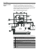
Figure P.1 DC SCR Precharge Module Block Diagram
The primary electrical components for the DC SCR Precharge Module are:
Precharge_Complete
CR
CR
CR CR
TB2A-1
TB2A-3
Power Module Sub-Assembly
TB2A-6
TB1A-1
TB1A-2
TB1A-3
TB2A-4
TB2A-2
TB2A-5
TB2A-10
TB2A-9
TB2A-7
TB2A-8
TB2A-11
TB2A-12
11
12
10
9
8
7
J1
/CHARGE
AC LINE
+5V
COMMON
-15V
+15V
J1
7
5
6
8
J3
GND
J2
110
J1
14
GND
13
1
3
TB1
47
G
SCR
Diode
HK
F1 R1 R11
+DCin
-DC
+DCout
+DCout
-DC
+DCin
-DC
GATE
CATHODE
AK
1
TB2
3
-DC
K
A
T
T
Fan
1
Jumper
Busbar
DC Input Power
DC Output Power
A1
319433-AXX
Power Supply Board
A2
350840-AXX
DC Precharge
Control Board
1
+DCout
+DCin
Jumpers
➌
➊
➍
➏
➎
➐
➑
➋
Item Description
➊
SCR-Diode Power Module (Sub-Assembly) conducts the continuous DC bus current once
the precharge of the drive’s capacitor bank has been achieved. A diode in parallel with the
SCR provides energy regeneration up to the SCR Precharge Module nameplate Amp rating.
➋
Protection fuse is for over-current protection during precharge.
➌
Precharge Resistors limit the current during the charging of the drive’s capacitor bank when
power is initially applied to the drive.
➍
Power Supply PCB provides a logic power to the Precharge Control board.
➎
DC Precharge Control PCB generates the gating signal to the SCR Power Module.
➏
Control Relay enables the SCR gating signal.
➐
Terminal Block for interfacing the SCR Precharge Module with the drive’s main control circuit.
➑
Cooling Fan connected to a customer-supplied 120 VAC supply. The fan must run when the
SCR is gated.