
User Manual


Installation/Wiring 1-7
Power Connection for 1000A and 1600A DC SCR Precharge Modules
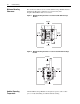
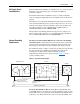
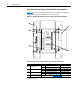
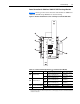
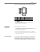
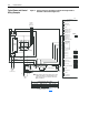
Figure 1.5 shows typical locations of bus bars and terminals on 1000A and
1600A DC SCR Precharge Modules for customer wiring.
Figure 1.5 Bus Bar and Terminal Locations for Wiring 1000A and 1600A Modules
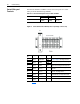
Table 1.C Power Connection Specifications for 1000A and 1600A Modules
Item Name Amps Bus Bars
(1)
(1)
Input/output power bus bar connections require the use of either lug-type connectors to terminate field-installed
conductors or bus bars.
Holes
➊
DC Bus +DCin
1000
76.2mm x 12.7mm (3.0 x 0.5 in.)
4 holes x 12.7mm (0.5 in.)
2 slots: 10mm x 20mm
(0.4 x 0.8 in.)
1600
76.2mm x 12.7mm (3.0 x 0.5 in.)
4 holes x 12.7mm (0.5 in.)
2 slots: 10mm x 20mm
(0.4 x 0.8 in.)
➋
DC Bus +DCout
1000
76.2mm x 12.7mm (3.0 x 0.5 in.)
4 holes x 12.7mm (0.5 in.)
2 slots: 10mm x 20mm
(0.4 x 0.8 in.)
1600
76.2mm x 12.7mm (3.0 x 0.5 in.)
4 holes x 12.7mm (0.5 in.)
2 slots: 10mm x 20mm
(0.4 x 0.8 in.)
➌
Protective Earth (GND)
1000 Bolt M10 x 25mm (0.984 in.) Torque 10Nm (88 lb-in.)
1600 Bolt M10 x 25mm (0.984 in.) Torque 10Nm (88 lb-in.)
➍
Control Terminal Blocks Refer to Table 1.D on page 1-8.
GND
+DCin
HKG
DANGER
DANGER
CAN CAUSE SHOCK
BURNS, OR DEATH
SURFACES
MAY BE HOT
REMOTE
SOURCE
+DCout
➌
➊
➍
➋
➍