
User Manual


1-8 Installation/Wiring
Control Wiring and
Terminals
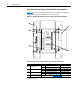
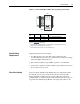
Terminal blocks TB1A and TB2A contain connection points for control
wiring of the DC SCR Precharge Module.
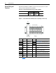
Table 1.D Control Terminal Specifications for TB1A and TB2A
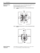
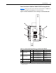
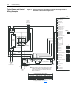
Figure 1.6 Control Terminal Block TB2A (located on precharge control board)
Name
Wire Size Range
(1)
(1)
Maximum/minimum sizes that the terminals will accept – these are not recommendations.
Torque
Maximum Minimum
Control Terminal Blocks
2.5 sq. mm
(14 AWG)
0.25 sq. mm
(22 AWG)
0.8 Nm
(7 lb.-in.)
Terminal
No.
Wiring Description Polarity Notes
1Customer-
supplied
120 VAC or
24 VDC Input
Phase
For interlocking with input system power. See
Start-Up on page 2-2 for voltage selection.
2 Neutral
3Customer-
supplied
120 VAC
Phase For supplying 120 VAC power to a cooling fan
4 Neutral
5
Customer-
supplied
120 VAC Phase
From external Normally Open contact that
energizes the Precharge Control Relay “CR”
6Customer-
supplied
Normally Open
contact
(1)
(1)
Refer to Appendix A for contact rating.
—
Output contacts from the Precharge Control
Relay “CR”
7
8—
Normally Closed
contact
(1)
—
Output contacts from the Precharge Control
Relay CR - “Precharge Enable”
9Customer-
supplied
Normally Closed
contact
(1)
—
Thermo switch’s contacts that open if the
Power Module has over-temperature failure
10
11 — — — Spare
12 Customer-
supplied
Ground (GND) GND Ground for a cooling fan
3
1
2
4
5
6
7
8
10
11
12
9
F1
TB2A
1
2
Customer Side