
User Manual


Installation/Wiring 1-9
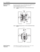
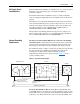
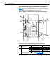
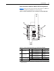
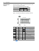
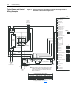
Figure 1.7 Control Terminal Block TB1A (located on precharge control board)
Control Wiring
Requirements
Important points about control wiring:
• Use Tinned-Copper wire only. Wire gauge requirements and
recommendations are based on 75°C (168°F). Do not reduce wire gauge
when using higher temperature wire.
• Wire with an insulation rating of 600V or greater is recommended.
• Control wires outside the cabinet should be separated from power wires
by at least 0.3 meters (1 foot).
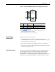
Drive Run Interlock
To protect the DC SCR Precharge Module from over-temperature failure,
the normally closed contacts of the thermo-switches on the DC SCR
Precharge Module should be wired to the Drive Run interlock circuit
(“Enable Input” or “Auxiliary Input”). This will ensure that the drive(s) are
stopped if a DC SCR Precharge Module over-temperature failure occurs.
Terminal
No.
Wiring Description Notes
1 — +DCin
(1)
(2)
(1)
Refer to Appendix A for contact rating.
(2)
Terminal TB1A-1 is supplied jumpered to +DCin, and TB1A-2 is supplied jumpered to +DCout.
Wiring to these terminals by the user is not required.
+DC (positive) Bus Input Power
2 — -DC
(1)
(3)
(3)
Terminal TB1A-2 must be wired to -DC of the drive by the user.
-DC (negative) Bus Power
3 — +DCout
(1)
(2)
+DC (positive) Bus Output Power
2
1
3
CR
TB1A
8765
4321
9
14
12 11 10
13