
Installation - A4 Size Owner's manual

10-14 Frame 13 Installation
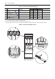
Table 10.C Frame 13 Power Terminal Specifications
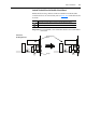
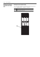
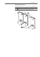
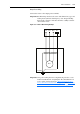
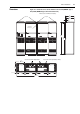
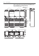
Figure 10.6 Frame 13 Drive Terminal Locations
No. Name Description
Wire Size Range
(1)(2)
Torque
Terminal Bolt Size
(3)(4)
Maximum Minimum Recommended
➊
Input Power Terminal Block
(1)
L1, L2, L3
Input power 300 mm
2
(600 MCM)
2.1 mm
2
(14 AWG)
40 N•m
(354 lb•in)
M12
➋
Output Power Terminal Block
(3)
U/T1, V/T2, W/T3
Motor connections 300 mm
2
(600 MCM)
2.1 mm
2
(14 AWG)
40 N•m
(354 lb•in)
M12
➌
SHLD Terminal, PE, Motor Ground
(3)
Terminating point for wiring shields 300 mm
2
(600 MCM)
2.1 mm
2
(14 AWG)
40 N•m
(354 lb•in)
M10
➍
DC Bus
(3)
(3 Terminals; DC–, DC+)
DC input or external brake 300 mm
2
(600 MCM)
2.1 mm
2
(14 AWG)
40 N•m
(354 lb•in)
M12
(1)
Maximum/minimum sizes that the terminal block will accept - these are not recommendations.
(2)
Do Not exceed maximum wire size. Parallel connections may be required.
(3)
These connections are bus bar type terminations and require the use of lug type connectors.
(4)
Apply counter torque to the nut on the other side of terminations when tightening or loosening the terminal bolt in order to avoid damage to the terminal.
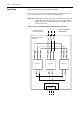
L3
L1
L2
DC-
DC+
DC-
DC+
DC-
DC+
U/T1 V/T2 W/T3
U/T1
V/T2 W/T3
Output Power
Terminals
➊
➍
➌
➋
Right enclosure shown only.