
Installation - A4 Size Owner's manual

PowerFlex
®
700H Control Wiring 2-11
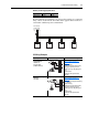
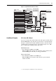
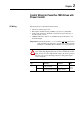
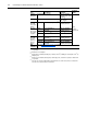
Figure 2.4 Speed Reference Selection Chart
(1)
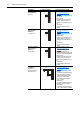
Auto/Manual Examples
PLC = Auto, HIM = Manual
A process is run by a PLC when in Auto mode and requires manual control
from the HIM during set-up. The Auto speed reference is issued by the PLC
through a communications module installed in the drive. Since the internal
communications is designated as Port 5, [Speed Ref A Sel] is set to “DPI
Port 5” with the drive running from the Auto source.
Attain Manual Control
• Press ALT then Auto/Man on the HIM.
When the HIM attains manual control, the drive speed command comes
from the HIM speed control keys or analog potentiometer.
Release to Auto Control
• Press ALT then Auto/Man on the HIM again.
When the HIM releases manual control, the drive speed command
returns to the PLC.
(1)
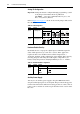
To access Preset Speed 1, set parameter 090 or 093 to “Preset Speed 1.”
= Default
Speed Ref B Sel, Parameter 093
Preset Speed 2, Parameter 102
Preset Speed 3, Parameter 103
Preset Speed 4, Parameter 104
Preset Speed 5, Parameter 105
Preset Speed 6, Parameter 106
Preset Speed 7, Parameter 107
TB Man Ref Sel, Parameter 096
Digital Input
DPI Port Ref 1-6, See Parameter 209 DPI Command
Jog Speed, Parameter 100
Jog Command
HIM Requesting Auto/Manual
Tr im
[Digital Inx Select]:
Speed Sel
3 21
001
011
010
100
101
110
111
Auto
Man
Drive Ref Rslt
Commanded
Frequency
Min/Max Speed
Acc/Dec Ramp
and
S Curve
Pure Reference
Post Ramp
to follower drive for
Frequency Referenc
e
to follower drive for
Frequency Referenc
e
Auto Speed Ref Options
Manual Speed Ref Options
Slip Compensation
1 "Slip Comp"
None
0 "Open Loop"
PI Output 2 "Process Pi"
Speed Adders [Speed Mode]:
PI Exclusive Mode
[PI Configuration]:
Bit 0, Excl Mode = 0
Output Frequency
Mod Functions
(Skip, Clamp,
Direction, etc.)
Speed Ref A Sel, Parameter 090
000