
Installation - A4 Size Owner's manual


Control Wiring for PowerFlex 700S Drives with Phase I Control 3-15
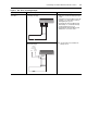
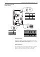
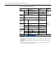
Figure 3.4 TB2 - Row B (Bottom) Wiring Examples
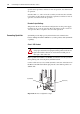
Hardware Enable Circuitry
The PowerFlex 700S provides a dedicated hardware enable input for
applications that require the drive to be disabled without software
interpretation.
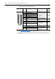
Input/Output Connection Example Required Parameter Changes
Secondary Encoder Interface
- Supports 12V dc differential
encoders with internal power
supply.
5V dc differential encoders
require external power supply
and special jumper settings.
Refer to Auxiliary Power
Supply on page 3-16 for
external power supply and
jumper settings.
For 5V dc differential encoders
with internal power supply, set
Jumper J6 to positions T2 and
T3.
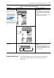
Secondary Encoder - using internal power supply Example: Using Encoder 1 for Primary Motor
Speed Feedback
• Set the value of Parameter 222 [Motor Fdbk
Sel] to 1 - “Encoder 1”, so the drive will use this
encoder as the primary motor speed feedback
device
• Set the value of Parameter 242 [Encoder1 PPR]
to match the encoder’s resolution
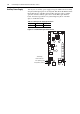
Secondary Encoder - using external power supply
Auxiliary Output - Relay
contact output
Auxiliary Output, Used to Indicate Running Example: Using Auxiliary Output to Indicate
Running
• Link Parameter 155 [Logic Status], the source,
to Parameter 841 [Relay Out Data], the sink
• Set Parameter 842 [Relay Out Bit] to 1, so that
Parameter 155 [Logic Status], bit 1 “Running”
will control the output.
1312111098721
Power
Common
(Return)
AA
BBZZ
Case Ground
13121110987
Power
Common
(Return)
AA
BBZZ
Case Ground
Shield
Power
Common
(Return)
45
Running
External
24V Powe
r
External
24V dc
Common
(Return)