
Installation - A4 Size Owner's manual
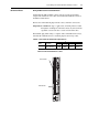
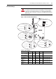

4-8 Control Wiring for PowerFlex 700S Drives with Phase II Control
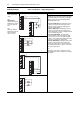
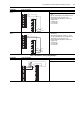
0-10V Analog Input 0-10V Analog Input - Bi-Polar na
0-10V Analog Input 0-10V Analog Input - External Source Required Parameter Changes
na
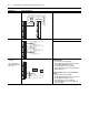
Analog Output
+/-10V DC
Used to drive analog
meters displaying speed
and current
0-10V Analog Output Using Analog Out 1, -10V to + 10V to meter Motor
RPM and direction:
• Send the data to the Analog Output
Par 833 [Anlg Out1 Real] (the destination) linked to
Par 71 [Filtered SpdFdbk] (the source)
• Scale the Output to the source parameter
Par 835 [Anlg Out1 Scale] = 175 (Par 4 [Motor NP
RPM] = 1750 / 10V)
Using Analog Out 2, -10V to + 10V to meter Motor
Current:
• Send the data to the Analog Output
Par 840 [Anlg Out2 Real] (the destination) linked to
Par 308 [Output Current] (the source)
• Scale the Output to the source parameter
Par 822 [Anlg Out2 Scale] = xx (Par 2 [Motor NP
FLA] / 10 V Output)
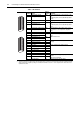
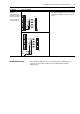
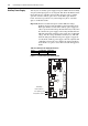
Input/Output Connection Example
1
2
3
4
5
6
7
8
9
10
11
12
13
14
15
16
17
18
19
20
21
22
23
24
-Signal or Source Common
+Signal
Shield / Common
-Signal or Source Common
+Signal
Shield / Common
-Signal or Source Common
+Signal
Shield / Common
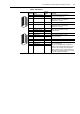
1
2
3
4
5
6
7
8
9
10
11
12
-
+
-
+
1
2
3
4
5
6
7
8
9
10
11
12