
Manual


Rockwell Automation Publication PFLEX-IN006E-EN-P - July 2013 27
General Installation Information Chapter 1
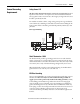
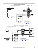
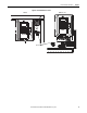
Figure 1 - Frame 9 Sample Precharge Wiring Diagram
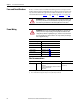
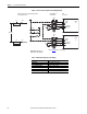
Figure 2 - Frames 10, 11 and 13 Sample Precharge Wiring Diagram
CR1
Pilot Relay
CR1
M
Main DC Contactor
M
CR2
Precharge
M
+24V DC
0V DC
Isolated
1
2
5
6
M
F2 R2 CR2
DC+
DC Source
DC-
CR2R1F1
M
Terminal Block on
Control Frame
Drive
Connections
Customer Connections - External Precharge Circuitry
is Shown as Dashed Lines
Important: For DC Input Only.
Do Not Install on DC Input Drives.
* Refer to Table 6
on page 28 for contact ratings.
CR1
Pilot Relay
CR1
M
Main DC Contactor
M
CR2
Precharge
M
Precharge
Complete
25
26
X15
X9
ASIC Board
X50
Charge
Relay*
21
23
25
26
21
23
M
F2 R2 CR2
DC+
DC Source
DC-
CR2R1F1
M
Customer Connections - External Precharge Circuitry
is Shown as Dashed Lines
Terminal Block on
Control Frame
Drive
Connections
Important: For DC Input Only.
Do Not Install on DC Input Drives.
* Refer to Tabl e 6
on page 28 for contact ratings.