
Manual


28 Rockwell Automation Publication PFLEX-IN006E-EN-P - July 2013
Chapter 1 General Installation Information
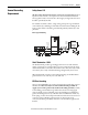
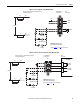
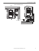
Figure 3 - Frames 12 and 14 Sample Precharge Wiring Diagram
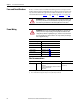
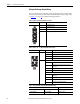
Table 6 - ASIC Board Charge Relay Contact Ratings
M
F2 R2 CR2
DC+
DC Source
DC-
CR2R1F1
M
ASIC
Board
#1
X9
X15
25
26
21
22
23
CR1
M
CR1
CR2
M
M
PU1
X50
Precharge
Complete*
21
23
25
26
Charge
Relay
ASIC
Board
#2
X9
X15
25
26
21
22
23
M
PU2
X50
Precharge
Complete*
21
23
25
26
Charge
Relay
Important: For DC Input Only.
Do Not Install on DC Input Drives.
* Refer to Table 6
below for contact ratings.
Customer Connections - External Precharge Circuitry
is Shown as Dashed Lines
Terminal Blocks on
Control Frame
Drive
Connections
Load Resistance load (cos φ = 1)
Rated load 8 A at 250 VAC: 5 A at 30 VDC
Rated carry current 8 A
Max. switching voltage 250 VAC; 30 VDC, (400 VAC)
Max. switching current AC 8 A; DC 5 A
Max. switching power 2,000 VA; 150 W
Failure rate (reference value) 5 VDC 10 mA (for gold plating 0.35 μ min.)