
Manual

Rockwell Automation Publication PFLEX-IN006E-EN-P - July 2013 35
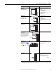
Control Wiring for PowerFlex 700H Drives Chapter 2
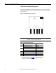
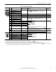
Table 10 - I/O Terminal Designations
No. Signal Factory Default Description
Related
Parameter(s)
1 Analog Input 1 (–)
(1) (2)
Isolated
(3)
, bipolar, differential, 9 bit & sign, 88 kΩ input impedance. A
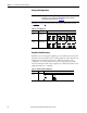
jumper (page 36) selects: 0…10V, ±10V,
0…20 mA. Default: 0…10V (Ri =200k), 4…20 mA (Ri=100 Ω).
320…327
2 Analog Input 1 (+)
(1)
3 Analog Input 2 (–)
(1)
4 Analog Input 2 (+)
(1)
5 –10V Pot Reference – 2 kΩ minimum, 10 mA maximum load, 1% accuracy.
6 Pot Common (GND) For (+) and (–) 10V pot references.
7 +10V Pot Reference – 2 kΩ minimum, 10 mA maximum load, 1% accuracy.
8Analog Output 1 (+)
(2)
Bipolar (current out is not bipolar), 9 bit and sign, 2 kΩ minimum load. A
jumper (page 36) selects: 0…10V, ±10V, 0…20 mA.
340…347
9Analog Output Common
10 Analog Output 2 (+)
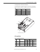
11 Digital Input 1 Stop - CF 115V AC, 50/60 Hz
- Opto isolated
Low State: less than 30V AC
High State: greater than 40V AC
24V DC
- Opto isolated (250V)
Low State: less than 5V DC
High State: greater than 20V DC
11.2 mA DC
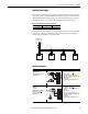
Enable: Digital Input 6 is jumper selectable for HW Enable (see page 36).
On-Time: < 16.7 ms, Off-Time < 1 ms
361…366
12 Digital Input 2 Start
13 Digital Input 3 Auto/Man
14 Digital Input 4 Speed Sel 1
15 Digital Input 5 Speed Sel 2
16 Digital Input 6/Hardware Enable Speed Sel 3
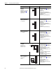
17 Digital Input Common Allows source or sink operation. Terminals 17, 18 and 19 can also be used
to provide backup power to DPI and control devices.
18
19 +24VDC
(4)
– Drive supplied logic input power.
20 24V Common
(4)
– Common for internal power supply.
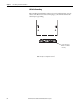
21 Digital Output 1 – N.C.
(5)
Fault Max. Resistive Load:
240V AC/30V DC – 1200VA, 150 W
Max. Current: 5 A, Min. Load: 10 mA
Max. Inductive Load:
240V AC/30V DC – 840VA, 105 W
Max. Current: 3.5 A, Min. Load: 10 mA
380…391
22 Digital Output 1 Common
23 Digital Output 1 – N.O.
(5)
NOT Fault
24 Digital Output 2 – N.C.
(5)
NOT Run
25 Digital Output 2/3 Com.
26 Digital Output 3 – N.O.
(5)
Run
(1) Important: Input must be configured with a jumper. Drive damage may occur if jumper is not installed properly. See page 36.
(2) These inputs/outputs are dependant on a number of parameters (see “Related Parameters” column in table).
(3) Differential Isolation - External source must be maintained at less than 160V with respect to PE. Input provides high common mode immunity.
(4) 150 mA maximum load. Not present on 115V versions. Can be used to provide control power from an external 24V source when main power is not applied. See page 36
.
(5) Contacts in un-powered state. Any relay programmed as Fault or Alarm will energize (pick up) when power is applied to drive and de-energize (drop out) when a fault or alarm exists. Relays selected for
other functions will energize only when that condition exists and will de-energize when condition is removed.
1
10
20
21