
Manual


46 Rockwell Automation Publication PFLEX-IN006E-EN-P - July 2013
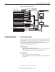
Chapter 3 Control Wiring for PowerFlex 700S Drives with Phase II Control
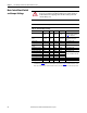
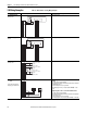
Main Control Board Switch
and Jumper Settings
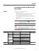
Table 15 - Switch and Jumper Settings
ATTENTION: The switches for Digital Inputs 4…6 are set to 24V DC at the
factory. If you are running a 115V AC input application, the switches must be set
as indicated below before applying power to the drive or damage to the main
control board may occur.
IMPORTANT
There are two separate values for an encoder
Function Default Switch Open Closed Notes
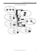
HW Enable Jumper (P22) pins 2-4
HW Enbl
SHUNT
Jumper
pins 2-4
HW Enbl
pins 1-3
No Enbl
No Jmpr = HW Enbl
See Hardware Enable Circuitry on
page 53
for configuration.
Gate Enable Jumper
(P13)
Jumper on
pins 15-16
SHUNT
Jumper
No Jmpr Jumper on
pins 15-16
No Jmpr = Gate disable or Safe-
Off/Second Encoder board is
present
(1)
(1) Refer to publication 20D-UM007, DriveGuard® Safe-Off Option for PowerFlex® 700S Phase II AC Drives and PowerFlex 700L Liquid-
Cooled AC Drives, for more information on the Safe-Off Option board, or publication, 20D-IN009
Installation Instructions - Second
Encoder Option Card for PowerFlex® 700S Drives with Phase II Control, for more information on the Second Encoder Option board.
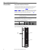
Analog Input 1 Voltage S5-2 Voltage Current Change with Power Off
Analog Input 2 Voltage S5-1 Voltage Current Change with Power Off
Digital Inputs 4-6
Voltage
24V DC S4-1,
S4-2
115V AC 24V DC Change with Power Off
Digital Input 1 Voltage 24V DC S3-1 24V DC 12V DC Change with Power Off
Digital Input 2 Voltage 24V DC S3-2 24V DC 12V DC Change with Power Off
Encoder Supply Voltage 12V DC S2-4 12V DC 5V DC Change with Power Off
Typically, set all switches the same
Encoder Signal A Voltage 12V DC S2-1 12V DC 5V DC
Encoder Signal B Voltage 12V DC S2-2 12V DC 5V DC
Encoder Signal Z Voltage 12V DC S2-3 12V DC 5V DC
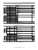
Function Switch Down Up Center Notes
DriveLogix Processor S1 RUN PROG REMOTE Processor Mode