
Manual

48 Rockwell Automation Publication PFLEX-IN006E-EN-P - July 2013
Chapter 3 Control Wiring for PowerFlex 700S Drives with Phase II Control
I/O Terminal Blocks
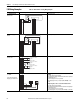
Wiring the Main Control Board I/O Terminals
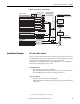
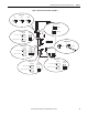
Terminal blocks TB1 and TB2 contain connection points for all inputs, outputs
and standard encoder connections. Both terminal blocks reside on the main
control board in the control cassette. See Figure 8
below for locations.
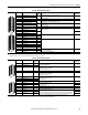
Table 17
and Table 18 on page 49 contain detailed descriptions for the terminals
on TB1 and TB2. Remove the terminal block plug from the socket and make the
appropriate connections. See Removing the Control Cassette on page 55
for
instructions on removing the control cassette from the drive.
Reinstall the plug when wiring is complete. The terminal blocks have keys, which
make it difficult to insert a terminal plug into the wrong socket.
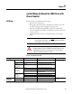
Table 16 - Control & Encoder Terminal Block Specifications
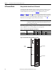
Figure 8 - Main Control Board I/O Terminal Block Locations
IMPORTANT
For NEMA/UL Type 1 applications, all wiring must be routed through the
conduit plate on the drive. Route any wires from the expanded cassette to the
base cassette and out of the drive.
Name Description Wires Size Range
(1)
(1) Maximum/minimum sizes the terminal block will accept - these are not recommendations.
Torque
Maximum Minimum Maximum Recommended
I/O Terminal Blocks Signal & Encoder power
connections
1.5 mm
2
(16 AWG)
0.14 mm
2
(28 AWG)
0.25 N•m
(2.2 lb•in)
0.22 N•m
(1.9 lb•in)
TB1 Terminals
TB2 Terminals
Control
Cassette