
Manual


Rockwell Automation Publication PFLEX-IN006E-EN-P - July 2013 49
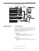
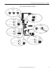
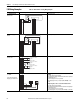
Control Wiring for PowerFlex 700S Drives with Phase II Control Chapter 3
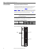
Table 17 - TB1 Terminal Descriptions
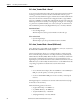
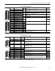
Table 18 - TB2 Terminal Descriptions
Terminal Signal Factory
Default
Description Related
Parameter
1 Analog Input 1 Comm. (Volt) Bipolar, differential input, +/-10V, 0-20 mA, 13 bit + sign
20 kΩ impedance at Volt; 500 Ω impedance at mA
(1)
800
2Analog Input 1 (+/-)
3 Shield NA Analog Input shield
4 Analog Input 2 Comm. (Volt) Bipolar, differential input, +/-10V, 0-20 mA, 13 bit + sign
20 kΩ impedance at Volt; 500 Ω impedance at mA
806
5Analog Input 2 (+/-)
6 Analog Input 3 [NTC-] Comm. (Volt) Differential input, 0-10V, 10 bit (for motor control mode FVC2, this is the temperature
adaptation input).
812
7Analog Input 3 [NTC+]
8 Shield NA Analog Output shield
9 Analog Output 1 (-) (Volt) Bipolar, differential output, +/-10V, 0-20 mA, 11 bit + sign
2 kΩ minimum load
832, 833
10 Analog Output 1 (+)
11 Analog Output 2 (-) (Volt) 839, 840
12 Analog Output 2 (+)
13 +10V Reference NA Rating: 20 mA maximum load (Recommend 5 kΩ pot)
14 Reference Common NA
15 -10V Reference NA
16 Encoder A NA Normal current draw per channel: 20 mA 230…233
17 Encoder A (Not) NA
18 Encoder B NA
19 Encoder B (Not) NA
20 Encoder Z NA
21 Encoder Z (Not) NA
22 Encoder Reference (+) NA 12 or 5V DC power supply for primary encoder interface
Rating: 300 mA maximum
23 Encoder Reference (-) NA
24 Encoder Shield NA Connection point for encoder shield
(1) The analog inputs are not isolated. However, the analog inputs can be connected in series when using current mode. Note that at 20 mA the voltage source must be capable of providing 10V DC at the drive
terminals for one drive - - 20V DC is required for two drives and 30V DC is required for three drives.
1
2
3
4
5
6
7
8
9
12
10
11
13
14
15
16
17
18
19
20
21
22
23
24
Terminal Signal Factory
Default
Description Related
Parameter
1 24V DC Common (-) NA Drive supplied 24V DC logic input power
Rating: 300 mA maximum load
2 24V DC Source (+) NA
3 Digital Output 1 24V DC Open Collector (sinking logic)
Rating: Internal Source = 150 mA max.
External Source = 750 mA
816, 847
4 Digital Output 1/2 Com NA Common for Digital Output 1 & 2
5 Digital Output 2 24V DC Open Collector (sinking logic)
Rating: Internal Source = 150 mA max.
External Source = 750 mA
851, 852
6 Relay Output 3 (NC) Relay contact output
Rating: 115V AC or 24V DC = 2 A max.
Inductive/Resistive
856, 857
7Relay Output 3 ComNA
8Relay Output 3 (NO)
9 Digital Input 1-3 Com NA Common for Digital Inputs 1-3
10 Digital Input 1 High speed 12V or 24V DC
(1)
, sinking
Load:15 mA at 24V DC
825
11 Digital Input 2 826
12 Digital Input 3 Load:15 mA at 24V DC sourcing 827
13 Digital Input 4-6 Com NA Common for Digital Inputs 4-6
14 Digital Input 4 Load: 10 mA at 24V DC sinking/sourcing
Load: 7.5 mA at 115V AC
Note: The 115 VAC Digital Inputs can withstand 2 mA of leakage current without turning on. If an
output device has a leakage current greater than 2 mA, a burden resistor is required. A 68.1 KΩ
resistor with a 0.5 W rating should be used to keep the 115 VAC output below 2 mA.
828
15 Digital Input 5 829
16 Digital Input 6 HW Enable 830
(1) Digital Inputs 1 and 2 are configured for 12V or 24V DC via DIP switches S3-1 and S3-2, respectively. 24V DC is the default setting.
1
2
3
4
5
6
7
8
9
10
11
12
13
14
15
16