
Manual


Rockwell Automation Publication PFLEX-IN006E-EN-P - July 2013 57
Chapter 4
Communication Options
Communication Module
Locations
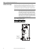
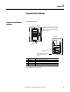
Figure 10 - DPI Port Locations
Note: DPI Port 4 is not available.
No. Connector Description
1 DPI Port 1 HIM connection when installed in the drive.
2 DPI Port 2 Cable connection for handheld and remote options.
3 DPI Port 3 or 2 Splitter cable connected to DPI Port 2 provides additional port.
4 DPI Port 5 Cable connection for communications adapter.
X1
X2
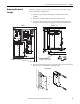
The HIM panel opens to allow access to the DPI
interface board on back side of panel. To open the
panel, remove the screws on left side of the HIM
panel and swing open.
Back View
To drive control (Main Control board
on 700S, DPI Interface board on
700H).
1
2, 3
4