
Manual


Rockwell Automation Publication PFLEX-IN006E-EN-P - July 2013 67
Frame 9 Mechanical Installation Chapter 5
Power Wiring
Table 22 - Power Terminal Specifications
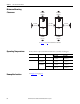
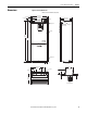
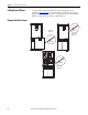
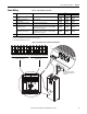
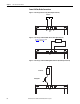
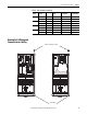
Figure 16 - Terminal Locations and Power Terminal Block
No. Name Description Wire Size Range
(1)
Torque
Maximum Minimum Recommended
1 Input Power Terminal Block
(2)
L1, L2, L3
Input power 185.0 mm
2
(350 MCM)
95.0 mm
2
(4/0 AWG)
40 N•m
(354 lb•in)
2 Output Power Terminal Block
(2)
U/T1, V/T2, W/T3
Motor connections 185.0 mm
2
(350 MCM)
95.0 mm
2
(4/0 AWG)
40 N
•m
(354 lb
•in)
3 SHLD Terminal, PE, Motor Ground Terminating point for wiring shields 95.0 mm
2
(4/0 AWG)
5.0 mm2
(10 AWG)
22 N•m
(195 lb•in)
4 DC Bus
(3)
(2 Terminals; DC–, DC+)
DC input or external brake resistor
(Internal Brake option not provided - See Frame 9 DC Bus/
Brake Connections on page 68.)
185.0 mm
2
(350 MCM)
95.0 mm
2
(4/0 AWG)
40 N•m
(354 lb•in)
DC Bus w/Brake
(3)
(3 Terminals; DC–, DC+/R+, R–)
DC input/internal brake
Internal Brake option not provided - See Frame 9 DC Bus/
Brake Connections on page 68.)
185.0 mm
2
(350 MCM)
95.0 mm
2
(4/0 AWG)
40 N•m
(354 lb•in)
5 Cable Clamp for Shield
(1) Maximum/minimum sizes that the terminal block will accept - these are not recommendations.
(2) Do Not exceed maximum wire size. Parallel connections may be required.
(3) DC terminal and brake lugs can be removed.
DC –
DC+/R+
R–
DC –
DC+/R+
R–
L1
AC Line Input Power To Motor Leads
L2 L3 L1 L2 L3 U/T1 V/T2 W/T3 U/T1 V/T2 W/T3
DC-, DC+/R+, R- terminals
shown with protective cover
removed.
1
2
3
4
5