
Manual


68 Rockwell Automation Publication PFLEX-IN006E-EN-P - July 2013
Chapter 5 Frame 9 Mechanical Installation
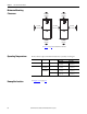
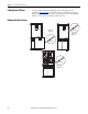
Frame 9 DC Bus/Brake Connections
Figure 17 - Connecting to DC Source Only (No Brake Option Ordered)
Figure 18 - Connecting to an External Brake Resistor (Brake Option Ordered)
Figure 19 - Connecting to an External Braking IGBT and Resistor (No Brake Option Ordered)
DC Source
DC– DC+/
R+
R–
DB Resistor
DC– DC+/
R+
R–
See Table 23
on page 69 for brake
resistor sizing information.
DB Resistor
DC– DC+/
R+
R–
Braking IGBT