
Instruction Manual
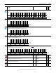
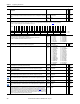
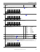
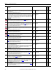
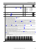
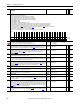
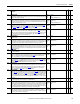
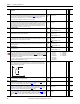
Table Of Contents
- PowerFlex 700S High Performance AC Drive - Phase II Control, Programming Manual
- Summary of Changes
- Table of Contents
- Preface
- Chapter 1 - Drive Start-Up
- Chapter 2 - Programming and Parameters
- Chapter 3 - Troubleshooting
- Appendix A - Human Interface Module Overview
- Appendix B - Application Notes
- Appendix C - Control Block Diagrams
- Appendix D - PowerFlex 700S Permanent Magnet Motor Specifications
- Appendix E - ATEX Approved PowerFlex 700S, Phase II Drives in Group II Category (2) Applications with ATEX Approved Motors
- Appendix F - History of Changes
- Index
- Back Cover
110 Rockwell Automation Publication 20D-PM001C-EN-P - July 2013
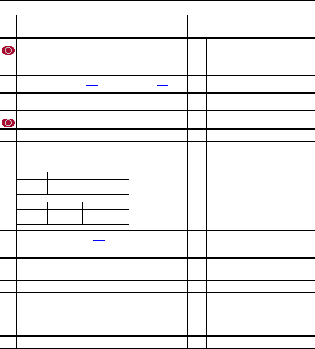
Chapter 2 Programming and Parameters
796 Posit Gear Ratio
Sets the load side gear ratio for position control. Adjust this value when the selection of Par 777 [PositionFdbk
Sel] is not 3 “Motor Fdbk”.
Calculation: Motor Encoder (Rpm) / Load Encoder (Rpm)
Note: This parameter was changed to non-linkable for firmware version 3.001. This parameter was changed to
be linkable for firmware version 3.004.
Default:
Min/Max:
1.00
0.00/9999.00
Y
RW Real
797 BasicIndx Step
Sets the amount added to or subtracted from Par 799 [BasicIndx Output] on a rising edge of Par 740 [Position
Control], bit 12 “BscIndx Step”. Note that this value can be positive or negative.
Default:
Min/Max:
0
-/+2147483648
Y
RW 32-bit
Integer
798 BasicIndx Preset
Sets the value to be moved into Par 799 [BasicIndx Output] when Par 740 [Position Control], bit 11 “BscIndx
Enbl” and bit 14 “BscIndx Prst” are both on.
Default:
Min/Max:
0
-/+2147483648
Y
RW 32-bit
Integer
799 BasicIndx Output
Displays the output of the Position Index function.
Default:
Min/Max:
0
-/+2147483648
RO 32-bit
Integer
800 Anlg In1 Data
Displays the scaled final value for Analog Input 1.
Default:
Min/Max:
0.0000
-/+2200000000.0000
RO Real
801 Anlg In1 Value
Displays the actual input value at Analog Input 1. Analog Input 1 may be configured for voltage or current input
signal. For proper selection of the input signal, the DIP switch S-5 and Par 821 [Analog I/O Units] must be set to
match. Par 801 [Anlg In1 Value] is multiplied by the value in Par 802
[Anlg In1 Scale] to produce the input to the
lead lag filter function.
Default:
Min/Max:
Units:
0.0000
-/+20.0000
V/mA
RO Real
802 Anlg In1 Scale
Scales the range of Analog Input 1 to the range of Par 800 [Anlg In1 Data]. Enter the units you want per volt or
mA. For example: If Par 801 [Anlg In1 Value] = 0 - 10V and you enter “6” in this parameter, Par 800 [Anlg In1
Data] will equal 0 - 60V.
Par 801 x Par 802 = Par 800.
Default:
Min/Max:
Units:
0.1000
-/+2200000000.0000
/V or /mA
Y
RW Real
803 Anlg In1 Offset
Applies an offset to Analog Input 1. Use the offset to correct for zero signal errors or to create an offset to the
actual input. The output of the A/D converter is summed with this parameter to produce Par 801 [Anlg In1
Value].
Default:
Min/Max:
Units:
0.0000
-/+20.0000
V/mA
Y
RW Real
804 AI 1 Filt Gain
Provides the Lead term for the Analog Input 1 filter.
Default:
Min/Max:
1.0000
-/+5.0000
Y
RW Real
805 Anlg In1 Filt BW
Provides the Lag term for the Analog Input 1 filter.
Default:
Min/Max:
Units:
0.0000
0.0000/3760.0000l
rad/s
Y
RW Real
806 Anlg In2 Data
Displays the scaled final value for Analog Input 2.
Default:
Min/Max:
0.0000
-/+2200000000.0000
RO Real
No. Name
Description
Values
Linkable
Read-Write
Data Type
Type of Input: Configurable, Voltage or Current
Polarity: Bi-Polar
Resolution: 14 bit (-8191 to +8191)
DIP Switch Analog I/O Units
AI 1 Voltage S5-2 = Open Par 821 Bit 0 = 0 (False)
AI 1 Current S5-2 = Closed Par 821 Bit 0 = 1 (True)
Light Heavy
Par 804
[Al 1 Filt Gain] 0.25 0.1
Par 805 [Anlg In1 Filt BW] 50 10