
Instruction Manual
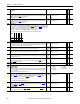
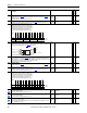
Table Of Contents
- PowerFlex 700S High Performance AC Drive - Phase II Control, Programming Manual
- Summary of Changes
- Table of Contents
- Preface
- Chapter 1 - Drive Start-Up
- Chapter 2 - Programming and Parameters
- Chapter 3 - Troubleshooting
- Appendix A - Human Interface Module Overview
- Appendix B - Application Notes
- Appendix C - Control Block Diagrams
- Appendix D - PowerFlex 700S Permanent Magnet Motor Specifications
- Appendix E - ATEX Approved PowerFlex 700S, Phase II Drives in Group II Category (2) Applications with ATEX Approved Motors
- Appendix F - History of Changes
- Index
- Back Cover
Rockwell Automation Publication 20D-PM001C-EN-P - July 2013 125
Programming and Parameters Chapter 2
1099 AddSub 1 Result
This is the result output from the Add and Subtract function. See Par 1096.
Equation: Par 1099
= (Par 1096 + Par 1097) - Par 1098
Note: This parameter was added for firmware version 3.001.
Default:
Min/Max:
1.0000
-/+2200000000.0000
RO Real
1100 AddSub 2 Input
Input value to be added to and/or subtracted from as need with the Add and Subtract function. This input will be
added with Par 1101
[AddSub 2 Add]. The result will be subtracted from by the value in Par 1102 [AddSub 2
Subtrct]. The result of the operation is loaded to Par 1103
[AddSub 2 Result].
Equation: Par (1100 + Par 1101) - Par 1102 = Par 1103
Note: This parameter was added for firmware version 3.001.
Default:
Min/Max:
1.0000
-/+2200000000.0000
Y RW Real
1101 AddSub 2 Add
This value is added to the value of Par 1100 [AddSub 2 Input]. The result will be subtracted from by Par 1102 and
loaded into Par 1103
. See Par 1100.
Note: This parameter was added for firmware version 3.001.
Default:
Min/Max:
1.0000
-/+2200000000.0000
Y
RW Real
1102 AddSub 2 Subtrct
This value is subtracted from the result of Par 1100 + Par 1101. The result will be loaded into Par 1103. See Par
1100.
Note: This parameter was added for firmware version 3.001.
Default:
Min/Max:
1.0000
-/+2200000000.0000
Y
RW Real
1103 AddSub 2 Result
This is the result output from the Add and Subtract function. See Par 1100.
Equation: Par 1103
= (Par 1100 + Par 1101) - Par 1102
Note: This parameter was added for firmware version 3.001.
Default:
Min/Max:
1.0000
-/+2200000000.0000
RO Real
1104 AddSub 3 Input
Input value to be added to and/or subtracted from as need with the Add and Subtract function. This input will be
added with Par 1105
[AddSub 3 Add]. The result will be subtracted from by the value in Par 1106 [AddSub 3
Subtrct]. The result of the operation is loaded to Par 1107 [AddSub 3 Result].
Equation: Par (1104 + Par 1105) - Par 1106 = Par 1107
Note: This parameter was added for firmware version 3.001.
Default:
Min/Max:
1.0000
-/+2200000000.0000
Y
RW Real
1105 AddSub 3 Add
This value is added to the value of Par 1104 [AddSub 3 Input]. The result will be subtracted from by Par 1106 and
loaded into Par 1107. See Par 1104.
Note: This parameter was added for firmware version 3.001.
Default:
Min/Max:
1.0000
-/+2200000000.0000
Y
RW Real
1106 AddSub 3 Subtrct
This value is subtracted from the result of Par 1104 + Par 1105. The result will be loaded into Par 1107. See Par
1104
Note: This parameter was added for firmware version 3.001.
Default:
Min/Max:
1.0000
-/+2200000000.0000
Y
RW Real
1107 AddSub 3 Result
This is the result output from the Add and Subtract function. See Par 1104.
Equation: Par 1107
= (Par 1104 + Par 1105) - Par 1106
Note: This parameter was added for firmware version 3.001.
Default:
Min/Max:
1.0000
-/+2200000000.0000
RO Real
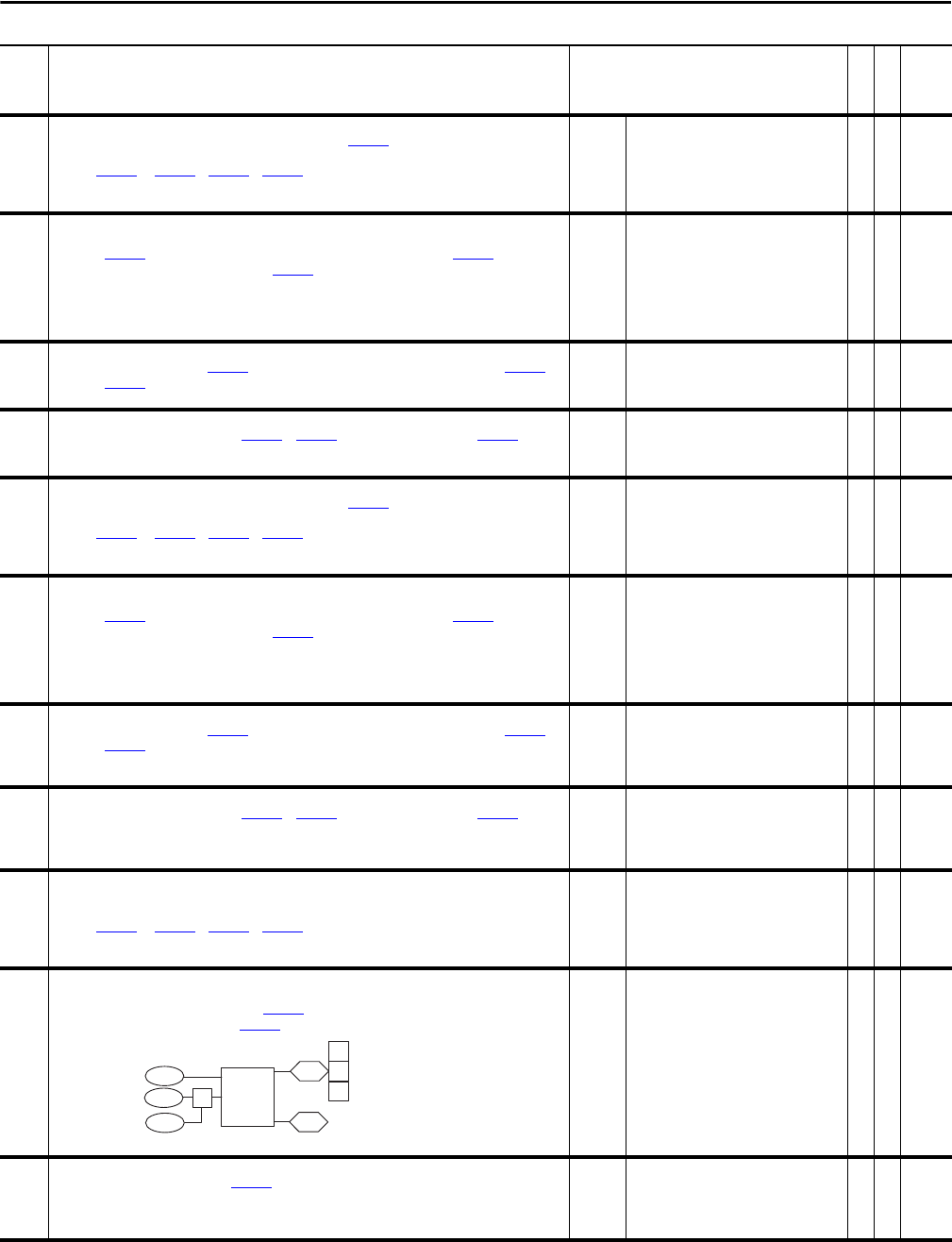
1108 DelTmr1 TrigData
Link a word to this parameter that will control a user-defined on or off delay timer. The bit within the selected
word that will control the delay timer is set by Par 1109
[DelTmr1 Trig Bit]. The user-defined on/off delay timer is
enabled by setting bit 6 “Delay Timer” of Par 1000
[UserFunct Enable].
Note: This parameter was added for firmware version 3.001.
Default:
Min/Max:
0
32 bits of data
Y
RW 32-bit
Boolean
1109 DelTmr1 Trig Bit
Selects the bit, from the word linked to Par 1108 [DelTmr1 TrigData], that will change the status of the user-
defined delay timer to on or off. When Par 1109 [DelTmr1 Trig Bit] is a positive number, the delay timer is an “on”
timer. When Par 1109 is a negative number, the delay timer is an “off” timer.
Note: This parameter was added for firmware version 3.001.
Default:
Min/Max:
0
-/+32
RW 16-bit
Integer
No. Name
Description
Values
Linkable
Read-Write
Data Type
Delay
Timer 1
1108
1112 00
DelayTimer 1 Data
1110
DelayTimer 1PrSet
1111
DelayTimer 1Stats
DelayTimer 1Accum
1109DelayTimer 1 Bit
00
00 Enabled
Timing
Done