
Instruction Manual
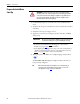
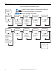

Table Of Contents
- PowerFlex 700S High Performance AC Drive - Phase II Control, Programming Manual
- Summary of Changes
- Table of Contents
- Preface
- Chapter 1 - Drive Start-Up
- Chapter 2 - Programming and Parameters
- Chapter 3 - Troubleshooting
- Appendix A - Human Interface Module Overview
- Appendix B - Application Notes
- Appendix C - Control Block Diagrams
- Appendix D - PowerFlex 700S Permanent Magnet Motor Specifications
- Appendix E - ATEX Approved PowerFlex 700S, Phase II Drives in Group II Category (2) Applications with ATEX Approved Motors
- Appendix F - History of Changes
- Index
- Back Cover
16 Rockwell Automation Publication 20D-PM001C-EN-P - July 2013
Chapter 1 Drive Start-Up
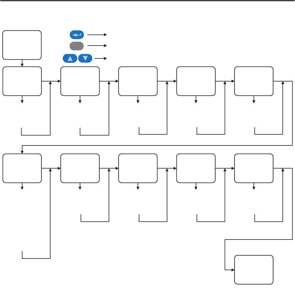
Figure 1 - PowerFlex 700S Assisted Start Routine Flow Chart
PowerFlex 700S
Start-Up
Motor Control Motor Data
Feedback
Configuration
Power Circuit
Test
Direction Test
Motor Tests Inertia Measure Speed Limits Speed Control Start / Stop / I/O
Select:
Motor Control Mode,
DB Resistor
Enter:
Motor NP Data,
Power & Units, FLA,
Volts, Hertz, RPM, Poles
Setup / Select:
Encoder, Resolver,
Hi-Res Encoder,
Linear Sensor
Diagnostic Check for:
Drive Power Circuit
Verify Direction
Field Oriented Control:
Measure: Stator
Resistance, Leakage
Inductance, Magnetizing
Inductance,
Slip Frequency
PMag Motor:
Measure: Encoder Offset,
Stator Resistance, Stator
Inductance, Back EMF
Measure:
System Inertia
Setup / Select:
Direction Control,
FWD, REV and
Absolute Speed Limits
Select:
Speed Reference
Sources
Done / Exit
Esc
Select a menu option or move down one level
Go back one selection or one level
Scroll through all choices
Configure: Digital Inputs,
Digital Outputs, Analog
Inputs, Analog Outputs